
How to Use FB: Examples, Pinouts, and Specs
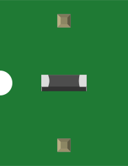
 Design with FB in Cirkit Designer
Introduction
The FB (Feedback) component is a crucial element in electronic circuits, designed to control the output by feeding a portion of it back to the input. This feedback mechanism is widely used to stabilize, amplify, or regulate signals in various systems. FB components are commonly found in amplifiers, oscillators, and control systems, where they play a vital role in ensuring consistent and predictable performance.
Explore Projects Built with FB
 Open Project in Cirkit Designer
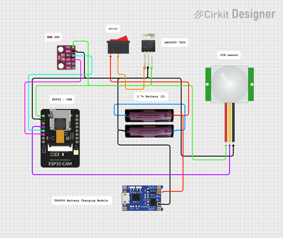 Open Project in Cirkit Designer
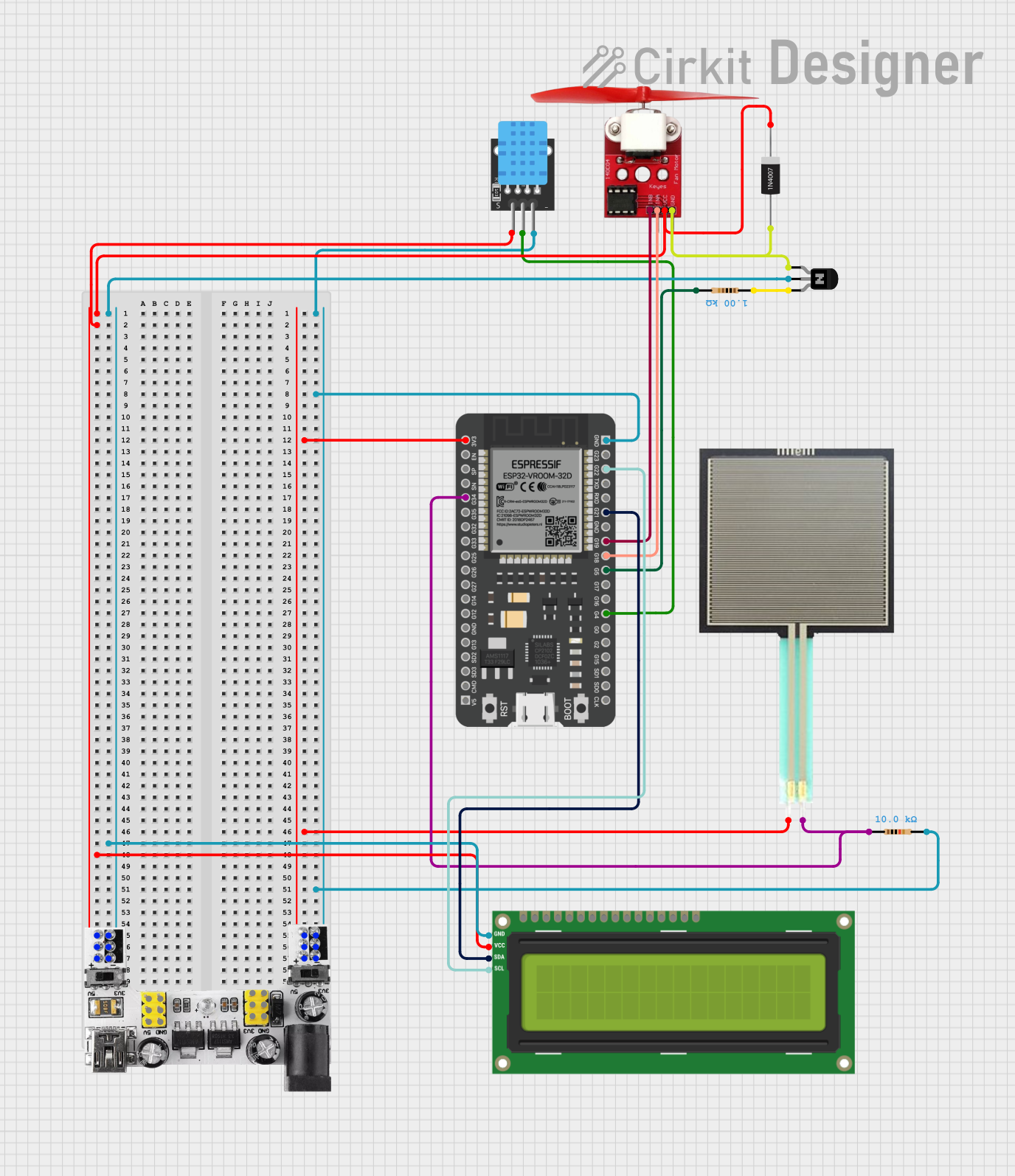 Open Project in Cirkit Designer
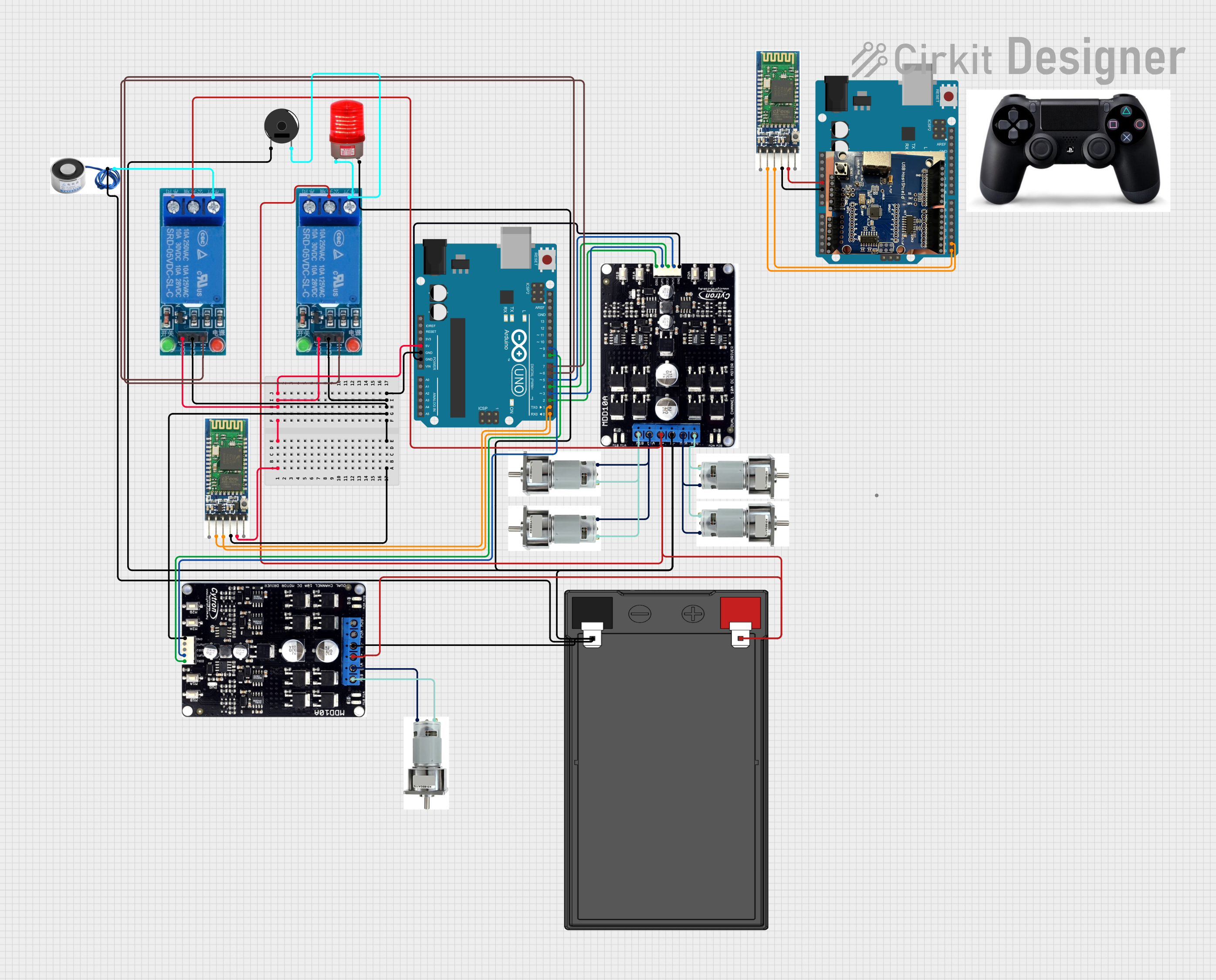 Open Project in Cirkit Designer
Explore Projects Built with FB
Open Project in Cirkit DesignerOpen Project in Cirkit DesignerOpen Project in Cirkit DesignerOpen Project in Cirkit DesignerCommon Applications and Use Cases
- Amplifiers: To control gain and improve stability.
- Oscillators: To sustain oscillations by providing positive feedback.
- Control Systems: To regulate system behavior and maintain desired output.
- Signal Processing: To filter, amplify, or modify signals.
- Power Supplies: To stabilize voltage and current outputs.
Technical Specifications
Key Technical Details
- Type: Passive or active feedback component (depending on the circuit design).
- Voltage Range: Typically operates within the circuit's supply voltage (e.g., 3.3V to 12V).
- Current Handling: Depends on the circuit configuration and associated components.
- Frequency Response: Suitable for low to high-frequency applications, depending on the design.
- Power Dissipation: Minimal, as it primarily redirects a portion of the signal.
Pin Configuration and Descriptions
The FB component does not have a standardized pinout, as its implementation depends on the circuit design. However, in most cases, it is represented as a feedback path or loop in the schematic. Below is an example of how it might be connected in an amplifier circuit:
| Pin Name | Description |
|---|---|
| Input Signal | The signal entering the circuit that requires feedback control. |
| Feedback Path | The portion of the output signal fed back to the input. |
| Output Signal | The controlled signal after feedback is applied. |
| Ground (GND) | Common ground connection for the circuit. |
Usage Instructions
How to Use the FB Component in a Circuit
- Identify the Feedback Type: Determine whether the circuit requires positive or negative feedback.
- Negative Feedback: Used to stabilize and linearize the circuit.
- Positive Feedback: Used to sustain oscillations or amplify signals.
- Connect the Feedback Path:
- For negative feedback, connect a portion of the output back to the inverting input.
- For positive feedback, connect a portion of the output back to the non-inverting input.
- Select Feedback Components: Use resistors, capacitors, or other components to control the feedback ratio and frequency response.
- Test the Circuit: Verify the circuit's performance and adjust the feedback components as needed.
Important Considerations and Best Practices
- Stability: Ensure that the feedback does not cause oscillations unless desired (e.g., in oscillators).
- Impedance Matching: Use appropriate resistor and capacitor values to avoid signal distortion.
- Power Ratings: Ensure that the feedback components can handle the circuit's voltage and current levels.
- Frequency Response: Design the feedback network to suit the desired frequency range of operation.
Example: Using FB in an Arduino UNO Circuit
Below is an example of using an FB component in a simple operational amplifier circuit connected to an Arduino UNO:
// Example: Reading a feedback-controlled amplifier output with Arduino UNO

const int feedbackPin = A0; // Analog pin to read the feedback-controlled output
int feedbackValue = 0;     // Variable to store the feedback signal value

void setup() {
  Serial.begin(9600); // Initialize serial communication at 9600 baud
}

void loop() {
  feedbackValue = analogRead(feedbackPin); // Read the feedback signal
  Serial.print("Feedback Signal Value: ");
  Serial.println(feedbackValue); // Print the feedback signal value to the Serial Monitor
  delay(500); // Wait for 500ms before the next reading
}
Note: In this example, the FB component is part of an external amplifier circuit. The Arduino reads the feedback-controlled output signal through an analog pin.
Troubleshooting and FAQs
Common Issues and Solutions
Oscillations in the Circuit:
- Cause: Incorrect feedback type or excessive feedback gain.
- Solution: Verify the feedback type (positive or negative) and adjust the feedback components to reduce gain.
Signal Distortion:
- Cause: Impedance mismatch or inappropriate feedback component values.
- Solution: Use resistors and capacitors with suitable values for the desired frequency range.
Unstable Output:
- Cause: Feedback loop delay or improper circuit design.
- Solution: Minimize feedback loop delay and ensure proper circuit layout.
No Output Signal:
- Cause: Feedback path not properly connected or broken.
- Solution: Check all connections and ensure the feedback path is intact.
FAQs
Q: Can I use an FB component in digital circuits?
- A: Yes, feedback mechanisms are also used in digital circuits, such as flip-flops and counters, to control state transitions.
Q: How do I calculate the feedback ratio?
- A: The feedback ratio is typically determined by the resistor and capacitor values in the feedback network. Use standard formulas for voltage dividers or frequency response calculations.
Q: What is the difference between positive and negative feedback?
- A: Positive feedback amplifies the input signal and can lead to oscillations, while negative feedback stabilizes the circuit and reduces distortion.
By following this documentation, users can effectively implement and troubleshoot FB components in their circuits.