How to Use Gravity: Analog Water Pressure Sensor: Examples, Pinouts, and Specs
Introduction
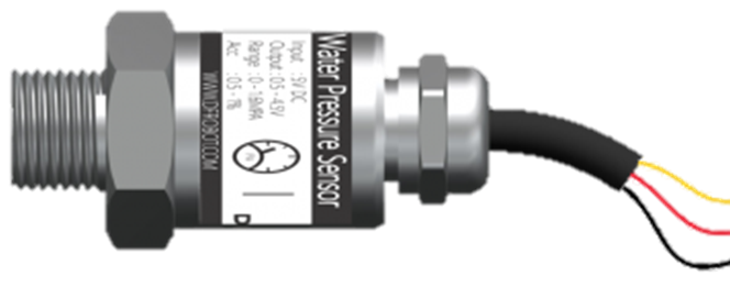
The Gravity: Analog Water Pressure Sensor (SEN0257) is a versatile and easy-to-use sensor designed to measure the pressure of water. Manufactured by DFRobot, this sensor is part of the Gravity series, which is known for its plug-and-play sensors that are compatible with a wide range of microcontrollers, including Arduino boards. The sensor outputs an analog signal that varies with the water pressure. It is commonly used in applications such as water conservation systems, tank water level sensing, and in DIY projects that involve fluid dynamics.
Explore Projects Built with Gravity: Analog Water Pressure Sensor
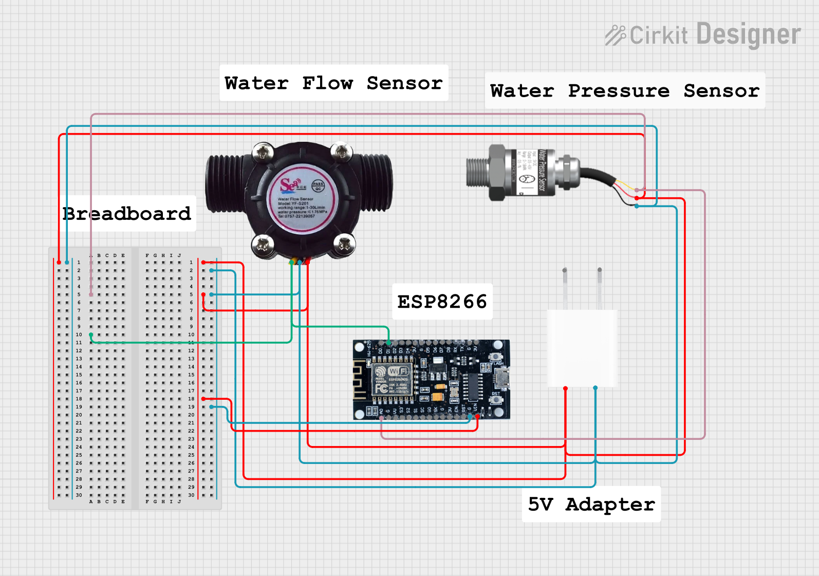
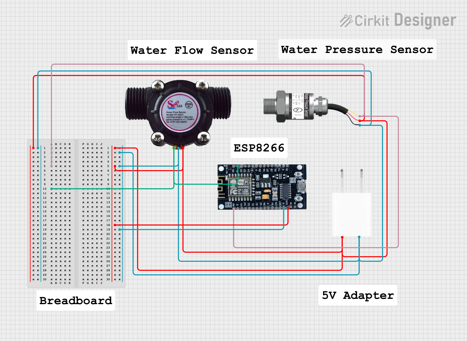
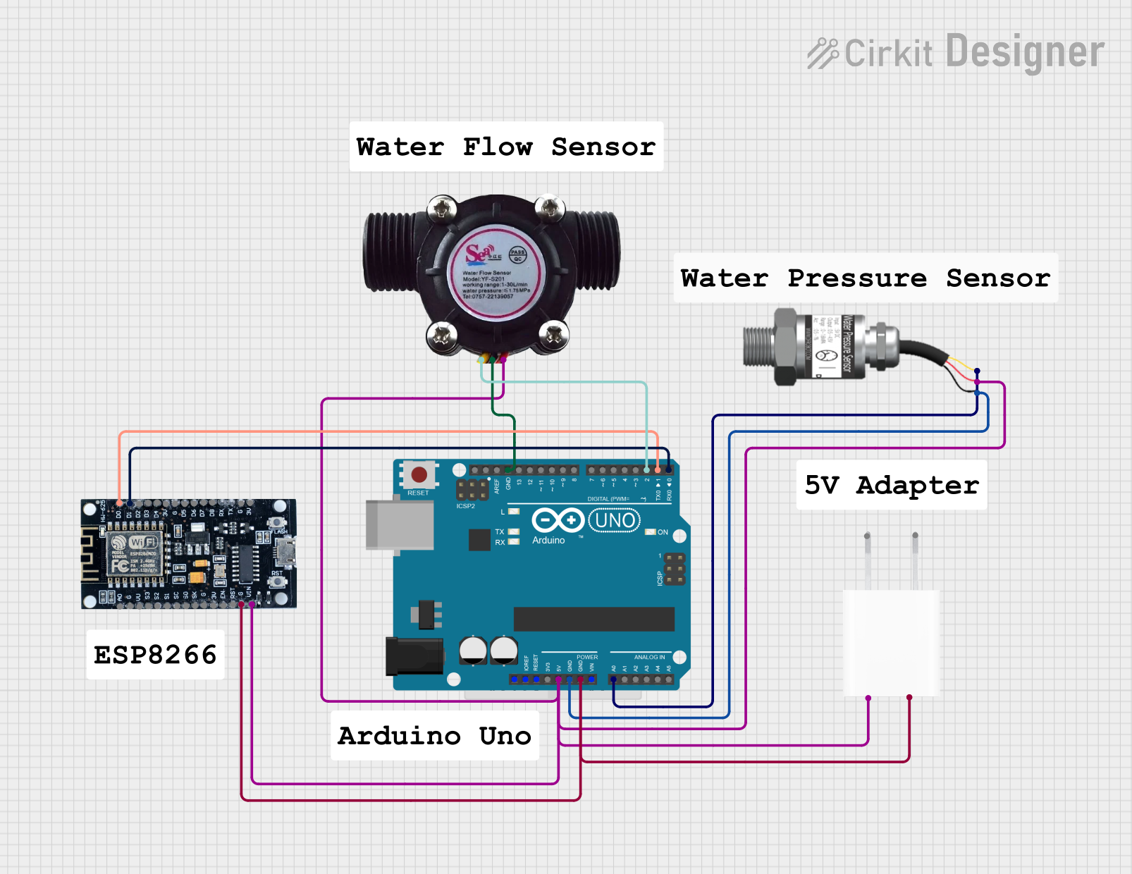
Explore Projects Built with Gravity: Analog Water Pressure Sensor
Technical Specifications
Key Technical Details
- Operating Voltage: 5V DC
- Measurement Range: 0-1.75 MPa (0-17.5 bar)
- Maximum Pressure: 2.0 MPa (20 bar)
- Accuracy: ±1.5% F.S.
- Output Signal: Analog (0.5-4.5V linear voltage output)
- Thread: 1/8" - 27 NPT
- Operating Temperature: -40°C to +85°C
- Response Time: ≤2.0 ms
Pin Configuration and Descriptions
| Pin Number | Signal | Description |
|---|---|---|
| 1 | VCC | Power supply (5V DC) |
| 2 | GND | Ground |
| 3 | Signal (V) | Analog voltage output proportional to pressure |
Usage Instructions
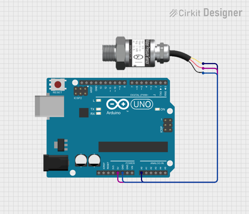
Connecting to a Circuit
- Connect the VCC pin to the 5V output on your microcontroller board.
- Connect the GND pin to the ground on your microcontroller board.
- Connect the Signal pin to an analog input on your microcontroller board.
Important Considerations and Best Practices
- Ensure that the power supply is stable and does not exceed 5V to prevent damage to the sensor.
- Use a pull-down or pull-up resistor if necessary to stabilize the analog signal.
- Avoid exposing the sensor to pressures beyond its maximum rating to prevent irreversible damage.
- When threading the sensor into a system, be careful not to over-tighten, which could damage the threads or the sensor itself.
- Calibrate the sensor in your specific application to account for any system-specific variances.
Example Code for Arduino UNO
// Define the analog input pin where the sensor is connected
const int pressureSensorPin = A0;

void setup() {
  // Initialize serial communication at 9600 bits per second:
  Serial.begin(9600);
}

void loop() {
  // Read the value from the sensor:
  int sensorValue = analogRead(pressureSensorPin);
  // Convert the analog reading (which goes from 0 - 1023) to a voltage (0 - 5V):
  float voltage = sensorValue * (5.0 / 1023.0);
  // Convert the voltage to pressure in MPa
  float pressure = (voltage - 0.5) * 1.75 / (4.5 - 0.5);

  // Print out the value in MPa
  Serial.print("Pressure: ");
  Serial.print(pressure);
  Serial.println(" MPa");

  // Delay for a bit to avoid spamming the serial output
  delay(500);
}
This code reads the analog output from the sensor and converts it to a voltage, then calculates the pressure in MPa based on the sensor's output characteristics.
Troubleshooting and FAQs
Common Issues
- Inaccurate Readings: Ensure that the sensor is properly calibrated for your specific application. Also, check for any electrical noise that might be affecting the analog signal.
- No Output Signal: Verify that all connections are secure and that the sensor is receiving the correct operating voltage.
- Sensor Damage: If the sensor has been exposed to pressures beyond its maximum rating, it may be damaged and require replacement.
Solutions and Tips for Troubleshooting
- Use shielded cables for the signal wire to reduce interference.
- Implement software filtering techniques to smooth out the analog signal if necessary.
- Regularly check the sensor for any physical damage or signs of wear.
FAQs
Q: Can this sensor be used with liquids other than water? A: The sensor is designed for use with water. Using it with other liquids may affect its accuracy and longevity.
Q: What is the meaning of the sensor's accuracy rating? A: The accuracy rating (±1.5% F.S.) means that the sensor's readings can vary by ±1.5% of the full-scale range, which is 1.75 MPa in this case.
Q: How can I calibrate the sensor? A: Calibration involves comparing the sensor's output to a known pressure reference and adjusting the output as necessary. This can be done through software or by using a calibration device.
Q: Is this sensor suitable for hot water applications? A: The sensor can operate within a temperature range of -40°C to +85°C. Ensure that the water temperature is within this range to avoid damaging the sensor.