How to Use Baterai LIfe : Examples, Pinouts, and Specs
Introduction
The Battery Life Indicator, commonly referred to as "Baterai LIfe," is an electronic component designed to measure and display the remaining charge of a battery. This component is essential for monitoring battery health and ensuring efficient power management in various applications. It is widely used in portable electronics, renewable energy systems, and electric vehicles to provide real-time feedback on battery status.
Explore Projects Built with Baterai LIfe


Explore Projects Built with Baterai LIfe
Common Applications and Use Cases
- Portable electronic devices (e.g., smartphones, tablets, and laptops)
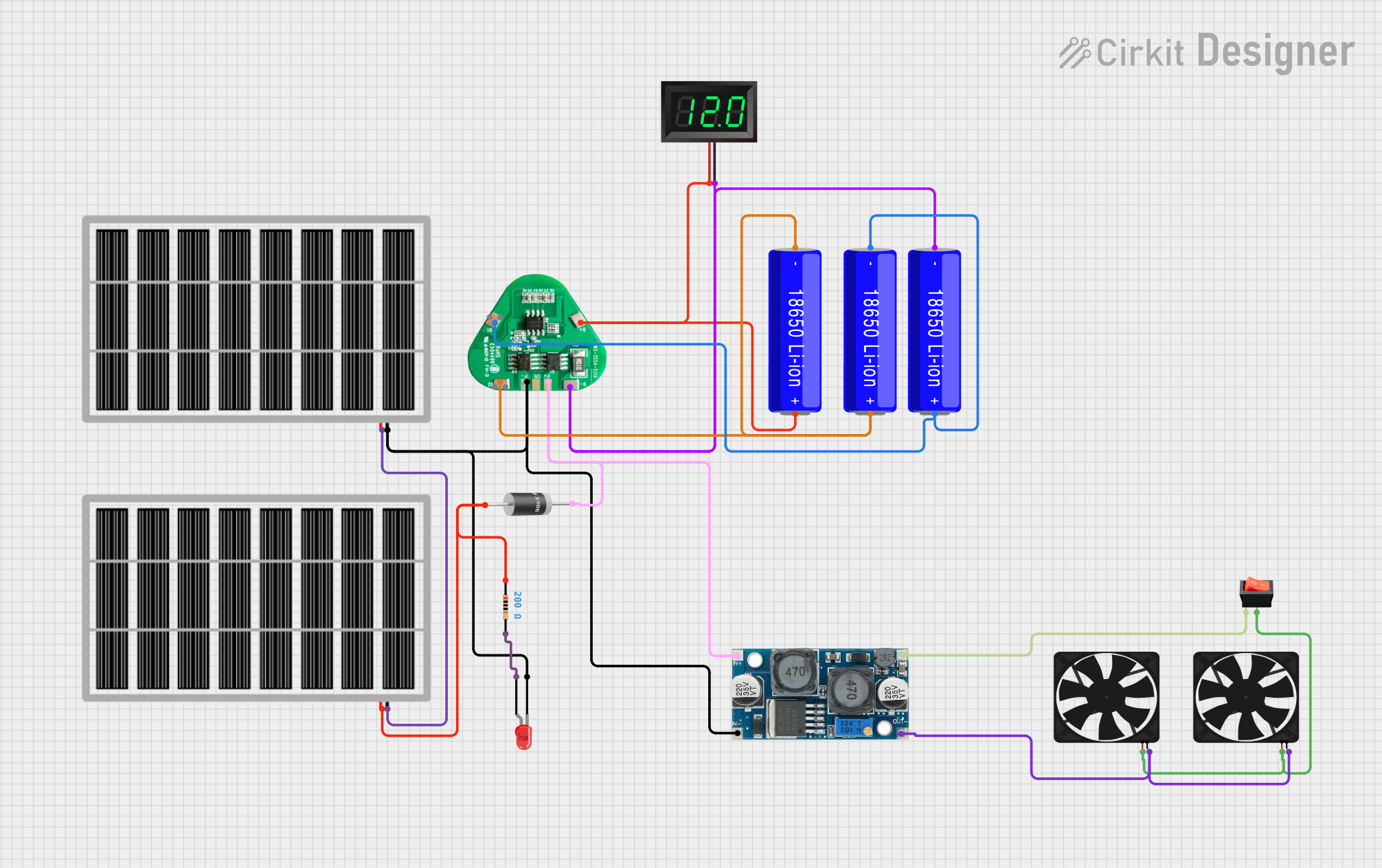
- Renewable energy systems (e.g., solar power storage monitoring)
- Electric vehicles and e-bikes
- Uninterruptible Power Supplies (UPS)
- DIY electronics projects requiring battery monitoring
Technical Specifications
The following table outlines the key technical details of the Baterai LIfe component:
| Parameter | Value |
|---|---|
| Operating Voltage | 3.3V - 5V |
| Operating Current | ≤ 15mA |
| Input Voltage Range | 0V - 25V |
| Display Type | LED bar graph or LCD (varies) |
| Accuracy | ±1% |
| Operating Temperature | -10°C to 60°C |
| Dimensions | 50mm x 25mm x 10mm |
Pin Configuration and Descriptions
The Baterai LIfe typically has the following pin configuration:
| Pin Name | Description |
|---|---|
| VCC | Power supply input (3.3V - 5V) |
| GND | Ground connection |
| BAT+ | Positive terminal of the battery to be monitored |
| BAT- | Negative terminal of the battery to be monitored |
| OUT | Optional output pin for interfacing with external microcontrollers or displays |
Usage Instructions
How to Use the Component in a Circuit
- Power the Component: Connect the VCC pin to a 3.3V or 5V power source and the GND pin to the ground.
- Connect the Battery: Attach the positive terminal of the battery to the BAT+ pin and the negative terminal to the BAT- pin.
- Observe the Display: The LED bar graph or LCD will display the remaining battery charge as a percentage or visual indicator.
- Optional Microcontroller Interface: If the component includes an OUT pin, connect it to an analog input pin of a microcontroller (e.g., Arduino UNO) for further processing or custom display.
Important Considerations and Best Practices
- Ensure the input voltage range of the battery matches the supported range of the Baterai LIfe (0V - 25V).
- Avoid reverse polarity connections to prevent damage to the component.
- Use appropriate resistors or voltage dividers if interfacing with batteries exceeding the input voltage range.
- For accurate readings, ensure the component is calibrated for the specific battery chemistry (e.g., Li-ion, NiMH).
Example: Connecting to an Arduino UNO
The following example demonstrates how to interface the Baterai LIfe with an Arduino UNO to read and display battery voltage:
// Arduino code to read battery voltage from the Baterai LIfe OUT pin
const int batteryPin = A0; // Connect the OUT pin of Baterai LIfe to Arduino A0
float batteryVoltage = 0.0;

void setup() {
  Serial.begin(9600); // Initialize serial communication for debugging
}

void loop() {
  int sensorValue = analogRead(batteryPin); // Read analog value from OUT pin
  batteryVoltage = (sensorValue / 1023.0) * 5.0 * 5;
  // Convert analog value to voltage. Adjust multiplier for voltage divider.

  Serial.print("Battery Voltage: ");
  Serial.print(batteryVoltage);
  Serial.println(" V");

  delay(1000); // Update every second
}
Note: If the battery voltage exceeds 5V, use a voltage divider to scale it down before connecting to the Arduino.
Troubleshooting and FAQs
Common Issues Users Might Face
No Display or Incorrect Readings:
- Cause: Incorrect wiring or insufficient power supply.
- Solution: Double-check all connections and ensure the VCC pin is supplied with 3.3V - 5V.
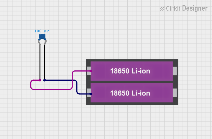
Flickering or Unstable Display:
- Cause: Noise or fluctuations in the battery voltage.
- Solution: Add a capacitor (e.g., 10µF) across the BAT+ and BAT- pins to stabilize the input.
Component Overheating:
- Cause: Exceeding the input voltage range or reverse polarity connection.
- Solution: Verify the battery voltage and polarity before connecting.
Inaccurate Battery Level Indication:
- Cause: Mismatch between the battery chemistry and the component's calibration.
- Solution: Use a component calibrated for the specific battery type or manually adjust the readings in software.
FAQs
Q1: Can the Baterai LIfe monitor multiple batteries simultaneously?
A1: No, the component is designed to monitor a single battery at a time. For multiple batteries, use a battery management system (BMS).
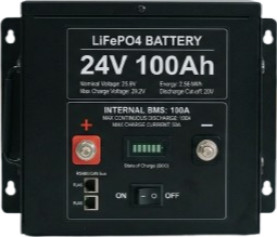
Q2: Is the Baterai LIfe compatible with LiFePO4 batteries?
A2: Yes, but ensure the voltage range of the battery is within the supported input range (0V - 25V).
Q3: Can I use the Baterai LIfe with a 12V car battery?
A3: Yes, the component supports 12V batteries. However, ensure proper connections and avoid exceeding the input voltage range.
Q4: How do I calibrate the component for different battery chemistries?
A4: Calibration can be done by adjusting the software (if interfaced with a microcontroller) or using a reference voltage source to fine-tune the readings.
By following this documentation, users can effectively integrate and utilize the Baterai LIfe component in their projects.