
How to Use LM393 Comparator Module: Examples, Pinouts, and Specs
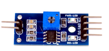
 Design with LM393 Comparator Module in Cirkit Designer
Introduction
The LM393 Comparator Module is a versatile electronic component designed to compare two input voltages and output a digital signal indicating which input is higher. It is based on the LM393 dual comparator IC, which operates with low power consumption and provides reliable performance. This module is widely used in applications such as voltage level detection, signal conditioning, and control systems. It is also commonly integrated into Arduino-based projects for tasks like sensor interfacing and threshold detection.
The module is manufactured by Generic and has the manufacturer part ID FC-37 Rain Sensor Module. While it is often used in conjunction with rain sensors, its functionality extends to a variety of other applications.
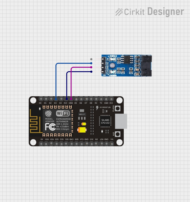
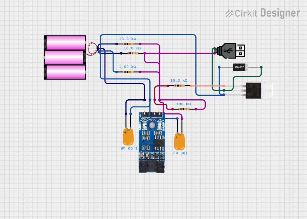
Explore Projects Built with LM393 Comparator Module
 Open Project in Cirkit Designer
 Open Project in Cirkit Designer
 Open Project in Cirkit Designer
 Open Project in Cirkit Designer
Explore Projects Built with LM393 Comparator Module
Open Project in Cirkit DesignerOpen Project in Cirkit DesignerOpen Project in Cirkit DesignerOpen Project in Cirkit DesignerTechnical Specifications
Below are the key technical details of the LM393 Comparator Module:
- Operating Voltage: 3.3V to 5V DC
- Output Type: Digital (High/Low)
- Comparator IC: LM393
- Output Current: Up to 16mA
- Input Voltage Range: 0V to Vcc
- Adjustable Threshold: Via onboard potentiometer
- Indicator LEDs: Power LED and Output Status LED
- Dimensions: Approximately 30mm x 20mm
Pin Configuration and Descriptions
The LM393 Comparator Module typically has a 4-pin interface. The pin configuration is as follows:
| Pin | Name | Description |
|---|---|---|
| 1 | VCC | Power supply input (3.3V to 5V DC). |
| 2 | GND | Ground connection. |
| 3 | DO (Digital Out) | Digital output signal. Outputs HIGH or LOW based on the comparison result. |
| 4 | AO (Analog Out) | Analog output signal. Provides the raw voltage from the sensor (if applicable). |
Usage Instructions
How to Use the LM393 Comparator Module in a Circuit
- Power the Module: Connect the
VCCpin to a 3.3V or 5V DC power source and theGNDpin to the ground of your circuit. - Input Signals: Provide the two input voltages to the comparator. One input is typically fixed as a reference voltage, which can be adjusted using the onboard potentiometer.
- Output Signal: The module outputs a digital HIGH (1) or LOW (0) signal on the
DOpin, depending on whether the input voltage exceeds the reference voltage. - Analog Output (Optional): If the module includes an analog output (
AO), you can use it to monitor the raw input voltage.
Important Considerations and Best Practices
- Adjusting the Threshold: Use the onboard potentiometer to set the reference voltage for comparison. Turning the potentiometer clockwise or counterclockwise changes the threshold.
- Power Supply: Ensure the module is powered within its operating voltage range (3.3V to 5V). Exceeding this range may damage the module.
- Output LEDs: The onboard LEDs provide visual feedback. The power LED indicates the module is powered, while the output LED lights up when the digital output is HIGH.
- Noise Filtering: If the input signal is noisy, consider adding a capacitor to filter out high-frequency noise.
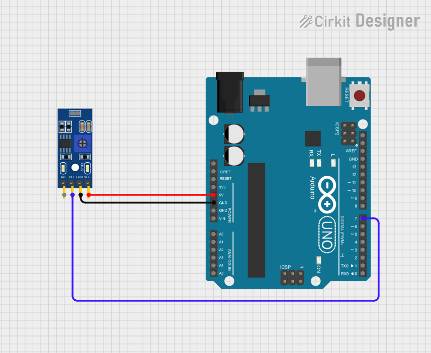
Example: Connecting to an Arduino UNO
Below is an example of how to connect and use the LM393 Comparator Module with an Arduino UNO:
Circuit Connections
- Connect the
VCCpin of the module to the 5V pin on the Arduino. - Connect the
GNDpin of the module to the GND pin on the Arduino. - Connect the
DOpin of the module to digital pin 2 on the Arduino.
Arduino Code
// LM393 Comparator Module Example with Arduino UNO
// This code reads the digital output (DO) from the module and prints the status
// to the Serial Monitor. The onboard LED on pin 13 will also indicate the status.

const int comparatorPin = 2; // Digital pin connected to DO pin of the module
const int ledPin = 13;       // Onboard LED pin

void setup() {
  pinMode(comparatorPin, INPUT); // Set comparator pin as input
  pinMode(ledPin, OUTPUT);       // Set LED pin as output
  Serial.begin(9600);            // Initialize serial communication
}

void loop() {
  int comparatorState = digitalRead(comparatorPin); // Read the digital output

  // Print the comparator state to the Serial Monitor
  if (comparatorState == HIGH) {
    Serial.println("Input voltage is HIGH (above threshold).");
    digitalWrite(ledPin, HIGH); // Turn on LED
  } else {
    Serial.println("Input voltage is LOW (below threshold).");
    digitalWrite(ledPin, LOW);  // Turn off LED
  }

  delay(500); // Wait for 500ms before the next reading
}
Troubleshooting and FAQs
Common Issues and Solutions
No Output Signal:
- Ensure the module is powered correctly (3.3V to 5V DC).
- Verify that the input voltages are within the module's operating range.
- Check the potentiometer setting and adjust it to set an appropriate threshold.
Output LED Not Working:
- Confirm that the power LED is lit. If not, check the power connections.
- Ensure the
DOpin is connected to the correct input pin on your microcontroller.
Unstable Output:
- Add a capacitor across the input pins to filter out noise.
- Verify that the input signals are stable and not fluctuating.
Analog Output Not Functioning:
- Ensure the
AOpin is connected to an analog input pin on your microcontroller. - Check if the module supports analog output, as some variants may not include this feature.
- Ensure the
FAQs
Q1: Can the LM393 Comparator Module work with a 3.3V microcontroller?
Yes, the module can operate at 3.3V, making it compatible with 3.3V microcontrollers like the ESP32 or Raspberry Pi Pico.
Q2: How do I adjust the sensitivity of the module?
The sensitivity can be adjusted by turning the onboard potentiometer. This changes the reference voltage used for comparison.
Q3: Can I use the module for AC voltage detection?
No, the module is designed for DC voltage comparison. For AC voltage detection, additional circuitry is required.
Q4: What is the maximum input voltage the module can handle?
The input voltage range is 0V to Vcc (typically 3.3V or 5V). Exceeding this range may damage the module.
By following this documentation, you can effectively integrate the LM393 Comparator Module into your projects and troubleshoot common issues with ease.