
How to Use esp32 : Examples, Pinouts, and Specs
 Design with esp32 in Cirkit Designer
Introduction
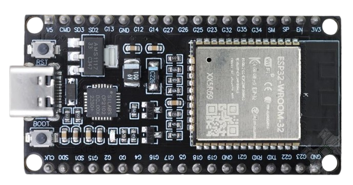
The ESP32 38P Type-C CP2102 is a versatile and powerful microcontroller module developed by Espressif Systems. It is based on the ESP32 dual-core processor, which integrates Wi-Fi and Bluetooth capabilities, making it ideal for IoT (Internet of Things) applications. This module features a USB Type-C interface for easy programming and power supply, as well as the CP2102 USB-to-UART bridge for seamless communication with a computer.
Common applications of the ESP32 38P Type-C CP2102 include:
- IoT devices and smart home automation
- Wireless sensor networks
- Wearable electronics
- Robotics and automation systems
- Prototyping and development of connected devices
Explore Projects Built with esp32
 Open Project in Cirkit Designer
 Open Project in Cirkit Designer
 Open Project in Cirkit Designer
 Open Project in Cirkit Designer
Explore Projects Built with esp32
Open Project in Cirkit DesignerOpen Project in Cirkit DesignerOpen Project in Cirkit DesignerOpen Project in Cirkit DesignerTechnical Specifications
The ESP32 38P Type-C CP2102 module has the following key technical specifications:
| Parameter | Value |
|---|---|
| Microcontroller | ESP32 dual-core Xtensa LX6 processor |
| Clock Speed | Up to 240 MHz |
| Flash Memory | 4 MB (varies by model) |
| SRAM | 520 KB |
| Wireless Connectivity | Wi-Fi 802.11 b/g/n, Bluetooth v4.2 + BLE |
| Operating Voltage | 3.3V |
| Input Voltage (via USB) | 5V (Type-C interface) |
| GPIO Pins | 38 (including ADC, DAC, PWM, I2C, SPI, UART, etc.) |
| USB-to-UART Bridge | CP2102 |
| Dimensions | Approximately 51mm x 25.5mm |
Pin Configuration and Descriptions
The ESP32 38P Type-C CP2102 module has 38 pins, each with specific functions. Below is a table summarizing the pin configuration:
| Pin Number | Pin Name | Function |
|---|---|---|
| 1 | GND | Ground |
| 2 | 3V3 | 3.3V power output |
| 3 | EN | Enable pin (active high, used to reset the module) |
| 4 | IO0 | GPIO0 (used for boot mode selection during programming) |
| 5 | IO1 | GPIO1 (UART TXD) |
| 6 | IO3 | GPIO3 (UART RXD) |
| 7 | IO4 | GPIO4 (PWM, ADC, or general-purpose GPIO) |
| 8 | IO5 | GPIO5 (PWM, ADC, or general-purpose GPIO) |
| 9 | IO12 | GPIO12 (ADC, touch sensor, or general-purpose GPIO) |
| 10 | IO13 | GPIO13 (ADC, touch sensor, or general-purpose GPIO) |
| ... | ... | ... (Refer to the official datasheet for the full pinout) |
| 38 | VIN | Input voltage (5V from USB or external power source) |
Note: Some pins have multiple functions (e.g., ADC, DAC, PWM, etc.). Refer to the ESP32 datasheet for detailed pin multiplexing information.
Usage Instructions
How to Use the ESP32 38P Type-C CP2102 in a Circuit
Powering the Module:
- Connect the module to a computer or power source using a USB Type-C cable. The onboard voltage regulator will convert the 5V input to 3.3V for the ESP32.
- Alternatively, supply 5V to the VIN pin or 3.3V to the 3V3 pin.
Programming the Module:
- Install the CP2102 USB-to-UART driver on your computer (if not already installed).
- Use the Arduino IDE or Espressif's ESP-IDF to write and upload code to the ESP32.
- Ensure GPIO0 is pulled LOW during programming to enable boot mode.
Connecting Peripherals:
- Use the GPIO pins to connect sensors, actuators, or other peripherals. Ensure the voltage levels are compatible (3.3V logic).
Wi-Fi and Bluetooth Setup:
- Use the built-in Wi-Fi and Bluetooth libraries in the Arduino IDE or ESP-IDF to configure wireless communication.
Important Considerations and Best Practices
- Voltage Levels: The ESP32 operates at 3.3V logic. Avoid connecting 5V signals directly to GPIO pins to prevent damage.
- Power Supply: Ensure a stable power supply, especially when using Wi-Fi or Bluetooth, as these features can cause current spikes.
- Pin Usage: Some pins (e.g., GPIO0, GPIO2, GPIO15) have specific roles during boot and should be used with caution.
- Heat Management: The ESP32 can get warm during operation. Ensure proper ventilation or heat dissipation if used in enclosed spaces.
Example Code for Arduino UNO Integration
Below is an example of using the ESP32 to control an LED via Wi-Fi:
#include <WiFi.h>

// Replace with your network credentials
const char* ssid = "Your_SSID";
const char* password = "Your_PASSWORD";

void setup() {
  Serial.begin(115200); // Initialize serial communication
  pinMode(2, OUTPUT);   // Set GPIO2 as an output pin (connected to an LED)

  // Connect to Wi-Fi
  Serial.print("Connecting to Wi-Fi");
  WiFi.begin(ssid, password);
  while (WiFi.status() != WL_CONNECTED) {
    delay(500);
    Serial.print(".");
  }
  Serial.println("\nWi-Fi connected!");
}

void loop() {
  digitalWrite(2, HIGH); // Turn the LED on
  delay(1000);           // Wait for 1 second
  digitalWrite(2, LOW);  // Turn the LED off
  delay(1000);           // Wait for 1 second
}
Note: Replace
Your_SSIDandYour_PASSWORDwith your Wi-Fi network credentials.
Troubleshooting and FAQs
Common Issues and Solutions
ESP32 Not Detected by Computer:
- Ensure the CP2102 driver is installed correctly.
- Try a different USB cable or port.
Failed to Upload Code:
- Check that GPIO0 is pulled LOW during programming.
- Verify the correct COM port and board settings in the Arduino IDE.
Wi-Fi Connection Issues:
- Double-check the SSID and password.
- Ensure the router is within range and supports 2.4 GHz Wi-Fi (ESP32 does not support 5 GHz).
Module Overheating:
- Reduce the workload or provide better ventilation.
- Check for short circuits or excessive current draw.
FAQs
Q: Can the ESP32 38P Type-C CP2102 be powered by batteries?
A: Yes, you can power the module using a 3.7V LiPo battery connected to the VIN pin (via a suitable regulator).Q: Does the module support OTA (Over-the-Air) updates?
A: Yes, the ESP32 supports OTA updates, allowing you to upload code wirelessly.Q: Can I use the ESP32 with MicroPython?
A: Yes, the ESP32 is compatible with MicroPython. You can flash the MicroPython firmware to the module and use Python for programming.Q: What is the maximum range of the Wi-Fi?
A: The Wi-Fi range depends on environmental factors but typically extends up to 100 meters in open spaces.
For additional support, refer to the official Espressif documentation or community forums.