How to Use Relay module 24V-5V: Examples, Pinouts, and Specs
Introduction
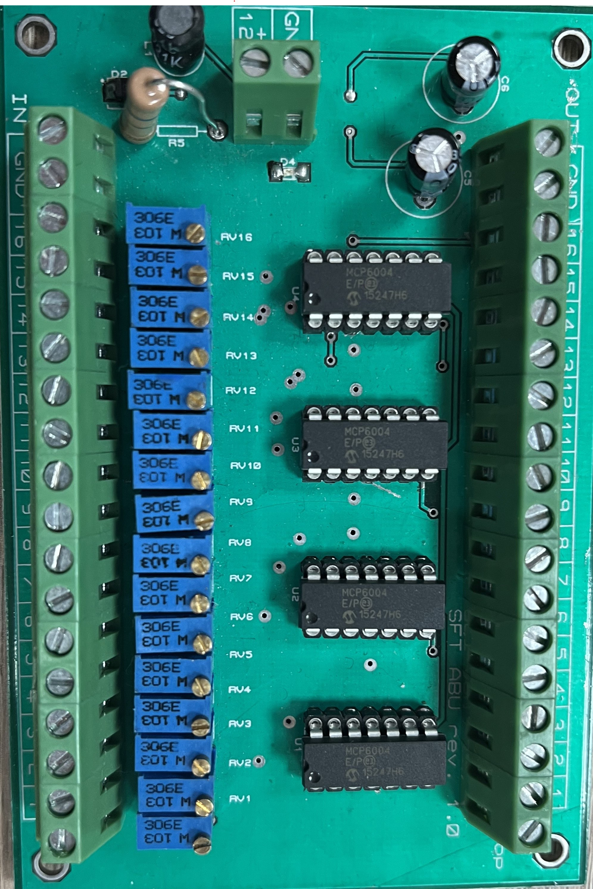
The Relay Module 24V-5V by SFT is an electronic switching device that enables the control of high-voltage devices using a low-voltage signal. This module is designed to switch between 24V and 5V, making it ideal for automation, control systems, and IoT applications. It is commonly used in projects where electrical isolation and high-power switching are required, such as home automation, industrial control, and robotics.
Explore Projects Built with Relay module 24V-5V


Explore Projects Built with Relay module 24V-5V
Common Applications:
- Home automation (e.g., controlling lights, fans, or appliances)
- Industrial equipment control
- Robotics and motor control
- IoT systems for remote device management
- Security systems (e.g., alarms or door locks)
Technical Specifications
The following table outlines the key technical details of the Relay Module 24V-5V:
| Parameter | Value |
|---|---|
| Operating Voltage | 5V DC (control side) |
| Switching Voltage | Up to 24V DC or 250V AC |
| Switching Current | Up to 10A |
| Trigger Voltage | 3.3V to 5V |
| Relay Type | SPDT (Single Pole Double Throw) |
| Isolation | Optocoupler-based isolation |
| Dimensions | 50mm x 25mm x 18mm |
| Manufacturer | SFT |
Pin Configuration and Descriptions
The relay module typically has the following pin configuration:
Control Side (Low Voltage)
| Pin Name | Description |
|---|---|
| VCC | 5V DC power supply for the module |
| GND | Ground connection |
| IN | Control signal input (3.3V to 5V logic) |
Output Side (High Voltage)
| Pin Name | Description |
|---|---|
| COM | Common terminal for the relay switch |
| NO | Normally Open terminal (connected when active) |
| NC | Normally Closed terminal (connected when inactive) |
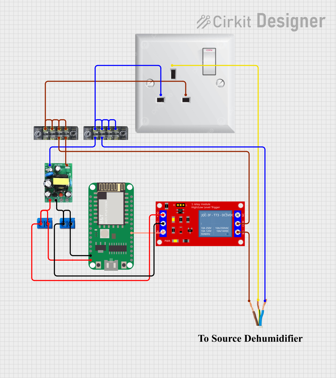
Usage Instructions
How to Use the Relay Module in a Circuit
- Power the Module: Connect the VCC pin to a 5V DC power source and the GND pin to the ground of your circuit.
- Control Signal: Connect the IN pin to a digital output pin of a microcontroller (e.g., Arduino UNO). A HIGH signal (3.3V or 5V) will activate the relay, while a LOW signal will deactivate it.
- Connect the Load:
- Connect the device you want to control (e.g., a light bulb or motor) to the COM and NO terminals for normally open operation.
- Alternatively, use the COM and NC terminals for normally closed operation.
- Isolation: Ensure proper electrical isolation between the control and output sides to prevent damage to the microcontroller.
Important Considerations
- Power Ratings: Do not exceed the relay's maximum voltage (24V DC or 250V AC) or current (10A).
- Flyback Diode: If controlling an inductive load (e.g., a motor), use a flyback diode across the load to protect the relay from voltage spikes.
- Safety: When working with high voltages, ensure proper insulation and follow safety guidelines to avoid electric shock.
Example: Connecting to an Arduino UNO
Below is an example of how to control the relay module using an Arduino UNO:
// Example: Controlling a Relay Module with Arduino UNO
// Pin Definitions
const int relayPin = 7; // Connect the IN pin of the relay to digital pin 7

void setup() {
  pinMode(relayPin, OUTPUT); // Set relay pin as an output
  digitalWrite(relayPin, LOW); // Ensure relay is off at startup
}

void loop() {
  digitalWrite(relayPin, HIGH); // Turn the relay ON
  delay(1000); // Wait for 1 second
  digitalWrite(relayPin, LOW); // Turn the relay OFF
  delay(1000); // Wait for 1 second
}
Notes:
- Replace
relayPinwith the appropriate pin number if using a different microcontroller. - Ensure the Arduino and relay module share a common ground.
Troubleshooting and FAQs
Common Issues and Solutions
Relay Not Activating:
- Cause: Insufficient control voltage.
- Solution: Ensure the IN pin receives a signal between 3.3V and 5V.
Load Not Switching:
- Cause: Incorrect wiring of the COM, NO, or NC terminals.
- Solution: Double-check the wiring and ensure the load is connected to the correct terminals.
Relay Stuck in One State:
- Cause: Damaged relay or excessive current draw.
- Solution: Verify the load does not exceed the relay's maximum current rating. Replace the relay if necessary.
Noise or Flickering:
- Cause: Electrical noise or insufficient power supply.
- Solution: Use a decoupling capacitor near the VCC and GND pins. Ensure a stable power source.
FAQs
Q1: Can I use this relay module with a 3.3V microcontroller like the ESP32?
A1: Yes, the relay module can be triggered with a 3.3V control signal. Ensure the VCC pin is still powered with 5V.
Q2: Is the relay module suitable for AC loads?
A2: Yes, the relay can switch AC loads up to 250V, provided the current does not exceed 10A.
Q3: Can I control multiple relays with one microcontroller?
A3: Yes, as long as each relay is connected to a separate digital output pin and the microcontroller can supply sufficient current.
Q4: How do I know if the relay is active?
A4: Most relay modules include an onboard LED that lights up when the relay is activated.
By following this documentation, you can effectively integrate the SFT Relay Module 24V-5V into your projects for reliable and efficient high-voltage control.