How to Use MAX 3232 MODULE: Examples, Pinouts, and Specs
Introduction
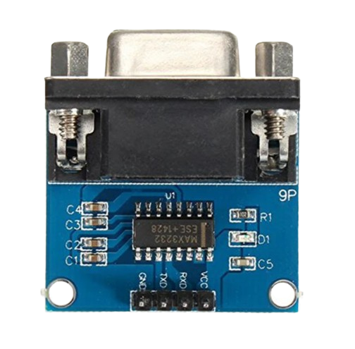
The MAX3232 module is a compact and efficient transceiver module designed for RS-232 communication. It serves as an interface between TTL or CMOS logic levels and RS-232 signal levels, making it an essential component for serial communication between microcontrollers, such as Arduino, and RS-232 compatible devices like PCs, GPS receivers, and industrial equipment. Its low-power consumption and wide voltage range make it suitable for battery-powered and portable applications.
Explore Projects Built with MAX 3232 MODULE
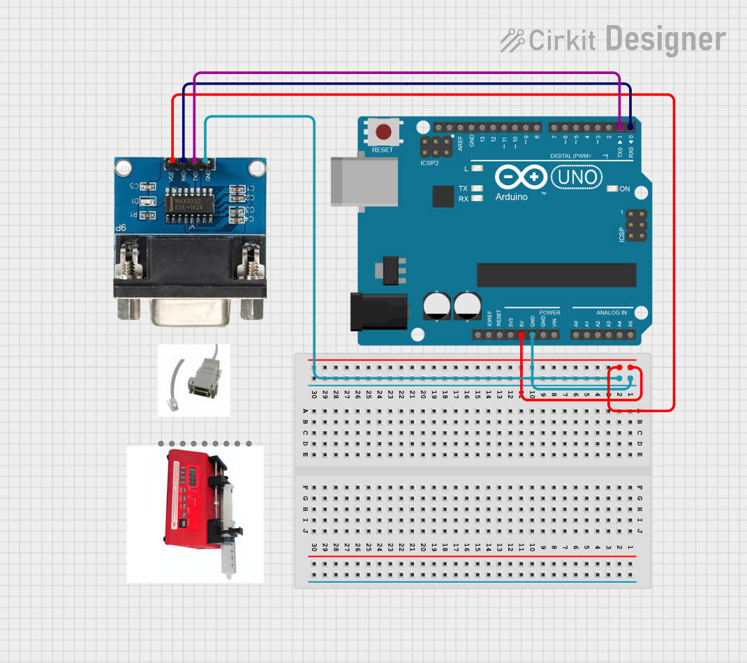
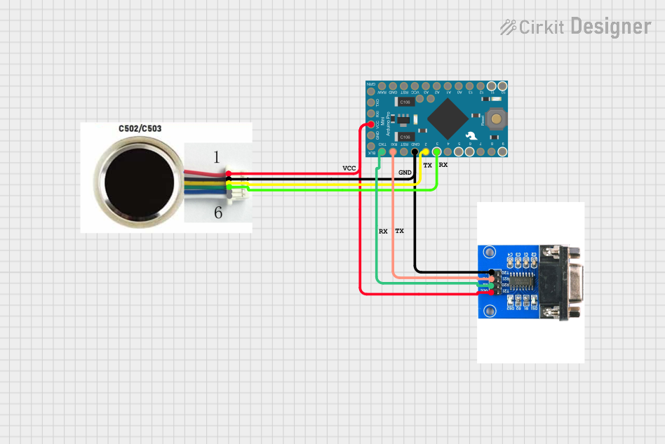
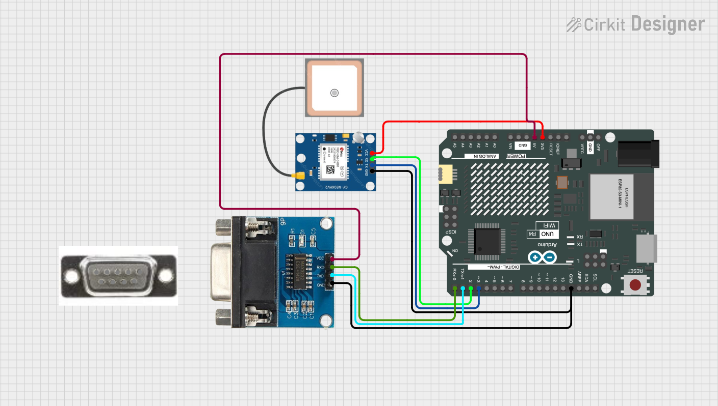

Explore Projects Built with MAX 3232 MODULE
Common Applications and Use Cases
- Serial communication between microcontrollers and RS-232 devices
- Data exchange with GPS modules, RFID readers, and sensors
- Interface for programming and debugging microcontrollers
- Conversion between computer serial ports and peripheral devices
Technical Specifications
Key Technical Details
- Supply Voltage (VCC): 3.0V to 5.5V
- Data Rate: Up to 250kbps
- Number of Receivers and Transmitters: 2 each
- Low-Power Shutdown Current: 1µA (Typical)
- ESD Protection: ±15kV Human Body Model
Pin Configuration and Descriptions
| Pin Number | Pin Name | Description |
|---|---|---|
| 1 | VCC | Power supply (3.0V to 5.5V) |
| 2 | GND | Ground |
| 3 | T1IN | TTL/CMOS transmit input 1 |
| 4 | R1OUT | RS-232 receive output 1 |
| 5 | R1IN | RS-232 receive input 1 |
| 6 | T1OUT | TTL/CMOS transmit output 1 |
| 7 | T2IN | TTL/CMOS transmit input 2 |
| 8 | R2OUT | RS-232 receive output 2 |
| 9 | R2IN | RS-232 receive input 2 |
| 10 | T2OUT | TTL/CMOS transmit output 2 |
Usage Instructions
How to Use the Component in a Circuit
- Power Supply: Connect the VCC pin to a 3.0V to 5.5V power source and the GND pin to the ground.
- TTL/CMOS Connection: Connect the T1IN and T2IN pins to the transmit pins of your microcontroller, and the T1OUT and T2OUT pins to the receive pins.
- RS-232 Connection: Connect the R1IN and R2IN pins to the RS-232 transmit lines, and the R1OUT and R2OUT pins to the RS-232 receive lines.
- Signal Ground: Ensure that the ground of the TTL/CMOS system and the RS-232 system are connected to establish a common reference point.
Important Considerations and Best Practices
- Use decoupling capacitors close to the power supply pins to minimize noise.
- Ensure proper ESD precautions when handling the module to prevent damage.
- Avoid running high-speed data lines parallel to power lines to reduce interference.
- Use twisted pair cables for RS-232 communication to enhance signal integrity.
Troubleshooting and FAQs
Common Issues Users Might Face
- No Communication: Check the power supply and connections. Ensure that the signal ground is connected between the TTL/CMOS system and the RS-232 system.
- Garbled Data: Verify the baud rate and data format settings on both devices. Use shielded cables if there is significant electromagnetic interference.
Solutions and Tips for Troubleshooting
- Double-check the wiring against the pin configuration table.
- Use an oscilloscope to verify the signal levels and integrity on both the TTL/CMOS and RS-232 sides.
- Ensure that the MAX3232 module is not exposed to voltages outside its specified range.
FAQs
Q: Can the MAX3232 module be used with a 3.3V microcontroller? A: Yes, the module operates with a supply voltage as low as 3.0V, making it compatible with 3.3V systems.
Q: Is level shifting necessary for 5V TTL signals? A: No, the MAX3232 can directly interface with 5V TTL signals without additional level shifting.
Q: How many devices can be connected to the MAX3232 module? A: The module can interface with up to two RS-232 devices simultaneously, with two receivers and two transmitters.
Example Code for Arduino UNO
#include <SoftwareSerial.h>

SoftwareSerial mySerial(10, 11); // RX, TX

void setup() {
  // Open serial communications:
  Serial.begin(9600);
  // Set the data rate for the SoftwareSerial port
  mySerial.begin(9600);
}

void loop() { // run over and over
  if (mySerial.available()) {
    Serial.write(mySerial.read());
  }
  if (Serial.available()) {
    mySerial.write(Serial.read());
  }
}
Note: This example uses the SoftwareSerial library to create a serial communication channel on pins 10 and 11 of the Arduino UNO, which are connected to the T1IN and T1OUT pins of the MAX3232 module, respectively. Adjust the pin numbers as needed for your specific setup.