How to Use NANO: Examples, Pinouts, and Specs
Introduction
The NANO is a compact microcontroller board based on the ATmega328P microcontroller. It is designed for small projects and prototyping, offering a balance of functionality and size. The NANO is highly versatile and compatible with most Arduino IDE libraries, making it an excellent choice for beginners and experienced developers alike. Its small form factor allows it to fit into tight spaces, making it ideal for embedded systems and portable applications.
Explore Projects Built with NANO
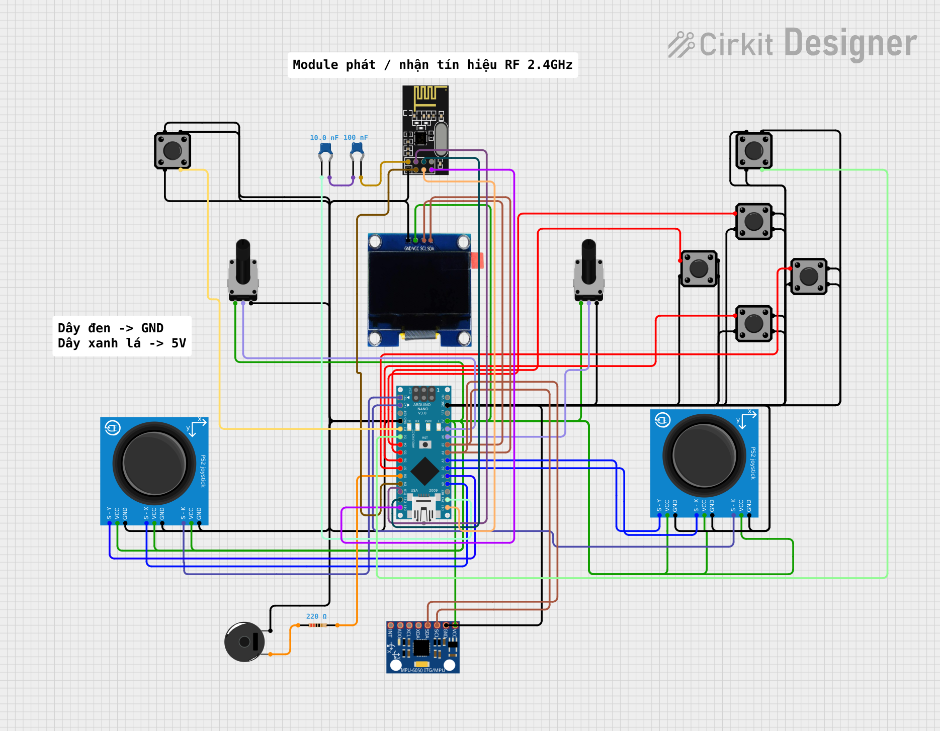
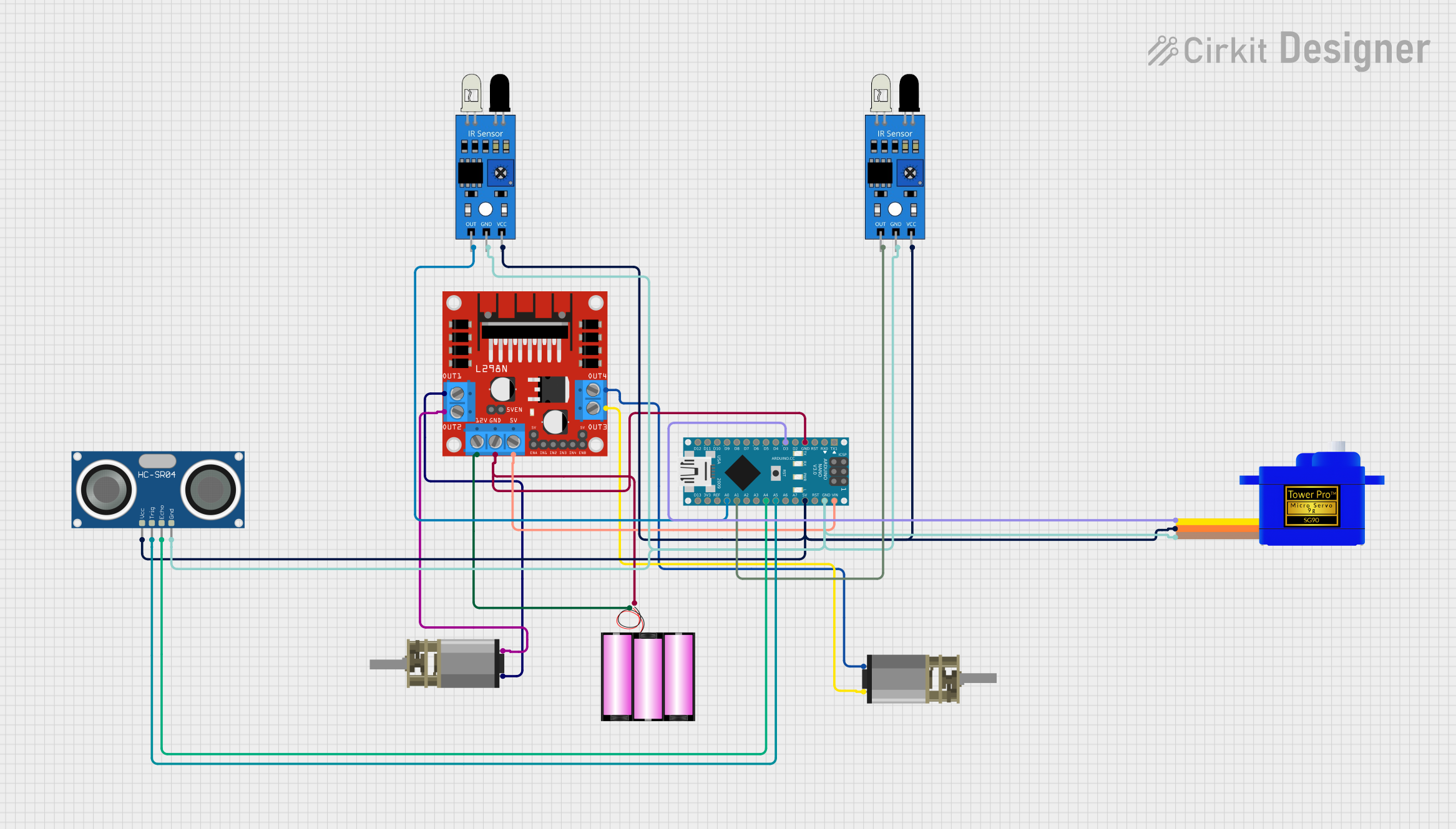
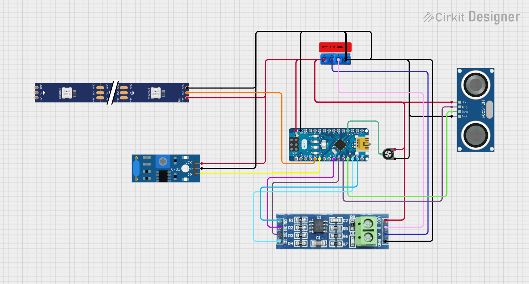
Explore Projects Built with NANO
Common Applications
- DIY electronics and prototyping
- Robotics and automation
- IoT (Internet of Things) devices
- Wearable technology
- Sensor-based projects
Technical Specifications
The NANO microcontroller board is equipped with the ATmega328P and features the following specifications:
| Specification | Details |
|---|---|
| Microcontroller | ATmega328P |
| Operating Voltage | 5V |
| Input Voltage (recommended) | 7-12V |
| Input Voltage (limit) | 6-20V |
| Digital I/O Pins | 14 (6 PWM outputs) |
| Analog Input Pins | 8 |
| DC Current per I/O Pin | 40 mA |
| Flash Memory | 32 KB (2 KB used by bootloader) |
| SRAM | 2 KB |
| EEPROM | 1 KB |
| Clock Speed | 16 MHz |
| Dimensions | 18 x 45 mm |
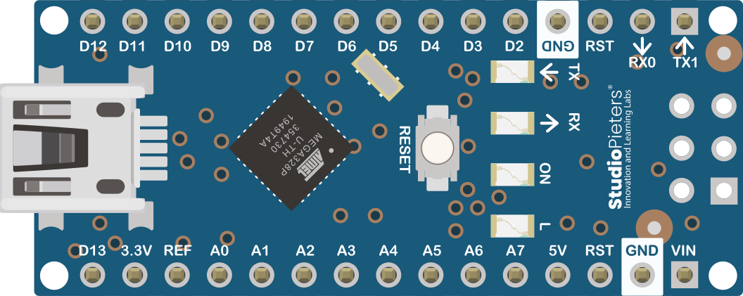
Pin Configuration and Descriptions
The NANO has a total of 30 pins, including power, analog, and digital pins. Below is a detailed description of the pin configuration:
Power Pins
| Pin | Description |
|---|---|
| VIN | Input voltage to the board when using an external power source (7-12V recommended). |
| 5V | Regulated 5V output from the onboard voltage regulator. |
| 3.3V | Regulated 3.3V output (maximum current: 50 mA). |
| GND | Ground pins (multiple GND pins available). |
| RESET | Resets the microcontroller when pulled LOW. |
Digital Pins
| Pin | Description |
|---|---|
| D0-D13 | Digital I/O pins. Pins D3, D5, D6, D9, D10, and D11 support PWM output. |
| TX (D1) | Transmit pin for serial communication. |
| RX (D0) | Receive pin for serial communication. |
Analog Pins
| Pin | Description |
|---|---|
| A0-A7 | Analog input pins (10-bit resolution). |
Other Pins
| Pin | Description |
|---|---|
| AREF | Reference voltage for analog inputs. |
| ICSP | In-Circuit Serial Programming header for programming the microcontroller. |
Usage Instructions
How to Use the NANO in a Circuit
- Powering the Board:
- Use the USB Mini-B connector to power the board via a computer or USB adapter.
- Alternatively, supply 7-12V to the VIN pin for external power.
- Connecting Components:
- Use the digital pins (D0-D13) for digital input/output operations.
- Use the analog pins (A0-A7) for reading analog signals from sensors.
- Connect external modules (e.g., sensors, motors) to the appropriate pins based on their voltage and current requirements.
- Programming the Board:
- Connect the NANO to your computer using a USB Mini-B cable.
- Open the Arduino IDE, select "Arduino Nano" as the board, and choose the correct processor (ATmega328P).
- Write your code and upload it to the board.
Example Code: Blinking an LED
The following example demonstrates how to blink an LED connected to pin D13:
// This example code blinks an LED connected to pin D13 on the NANO board.
// The LED will turn ON for 1 second and OFF for 1 second in a loop.

void setup() {
  pinMode(13, OUTPUT); // Set pin D13 as an output pin
}

void loop() {
  digitalWrite(13, HIGH); // Turn the LED ON
  delay(1000);            // Wait for 1 second
  digitalWrite(13, LOW);  // Turn the LED OFF
  delay(1000);            // Wait for 1 second
}
Important Considerations
- Avoid exceeding the maximum current rating (40 mA) for any I/O pin to prevent damage.
- Use appropriate resistors when connecting LEDs or other components to limit current.
- Ensure the input voltage to the VIN pin does not exceed 20V to avoid damaging the voltage regulator.
Troubleshooting and FAQs
Common Issues
The NANO is not detected by the computer:
- Ensure the USB cable is functional and supports data transfer.
- Install the correct USB-to-serial driver (e.g., CH340 driver for some NANO clones).
Code upload fails:
- Verify that the correct board and processor are selected in the Arduino IDE.
- Check the COM port settings in the IDE.
- Press the RESET button on the NANO before uploading the code.
Components connected to the NANO are not working:
- Double-check the wiring and connections.
- Ensure the components are compatible with the NANO's voltage and current ratings.
FAQs
Q: Can the NANO run on 3.3V?
A: Yes, the NANO can operate at 3.3V, but some features (e.g., clock speed) may be affected.
Q: How do I reset the NANO?
A: Press the RESET button on the board or pull the RESET pin LOW momentarily.
Q: Can I use the NANO with a breadboard?
A: Yes, the NANO's pin layout is designed to fit standard breadboards for easy prototyping.
By following this documentation, you can effectively use the NANO microcontroller board for a wide range of projects and applications.