
How to Use Raspberry Pi Pico 2 W: Examples, Pinouts, and Specs
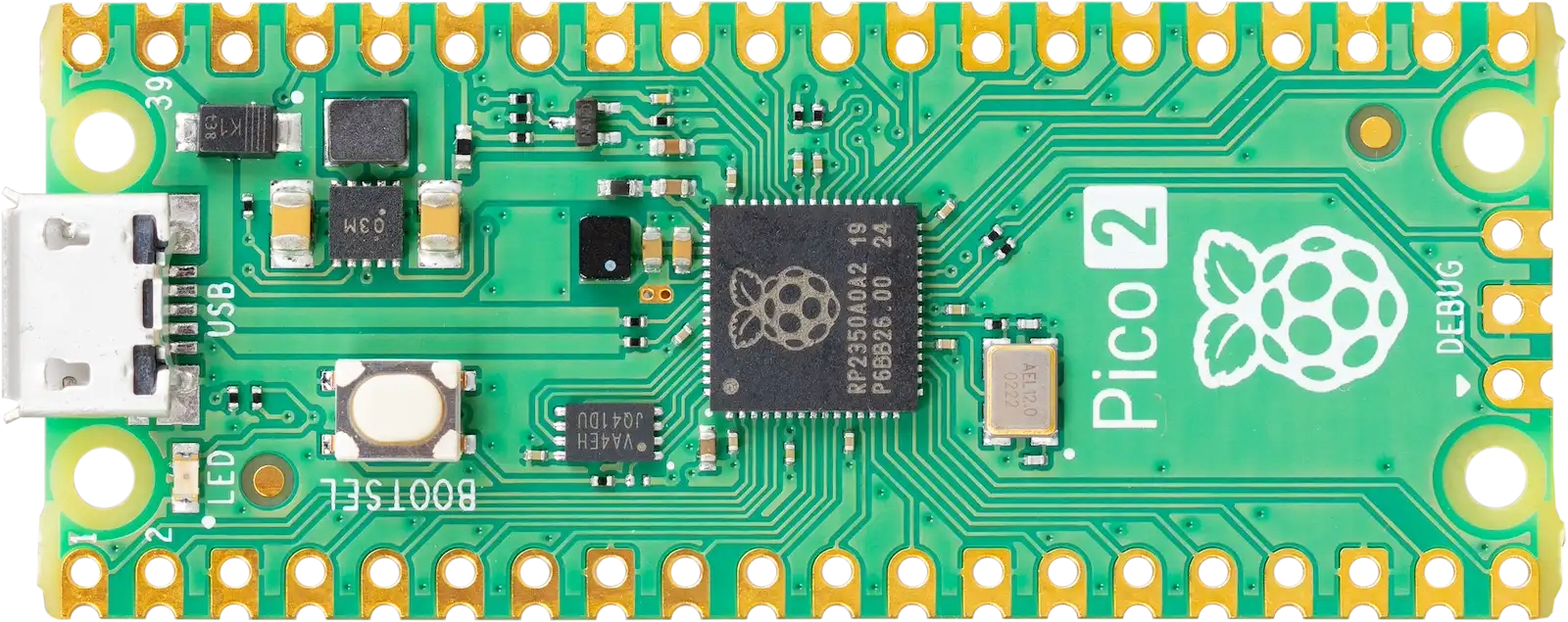
 Design with Raspberry Pi Pico 2 W in Cirkit Designer
Introduction
The Raspberry Pi Pico 2 W is a compact and versatile microcontroller board developed by Raspberry Pi. It features a dual-core ARM Cortex-M0+ processor, 2MB of onboard flash memory, and integrated Wi-Fi connectivity, making it an excellent choice for Internet of Things (IoT) projects, embedded systems, and general-purpose microcontroller applications. Its small form factor and low power consumption make it ideal for portable and battery-powered devices.
Explore Projects Built with Raspberry Pi Pico 2 W
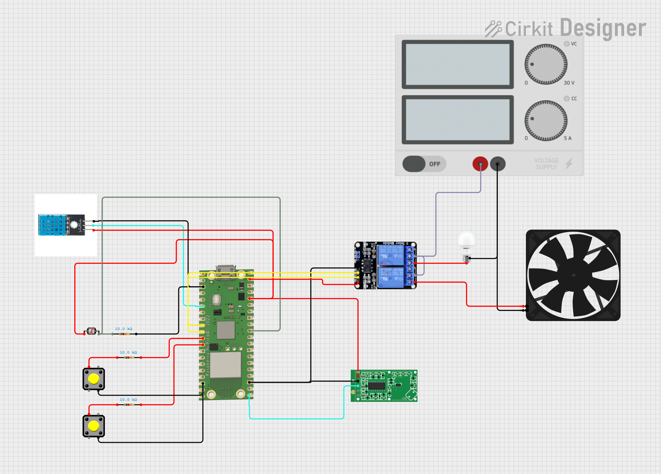 Open Project in Cirkit Designer
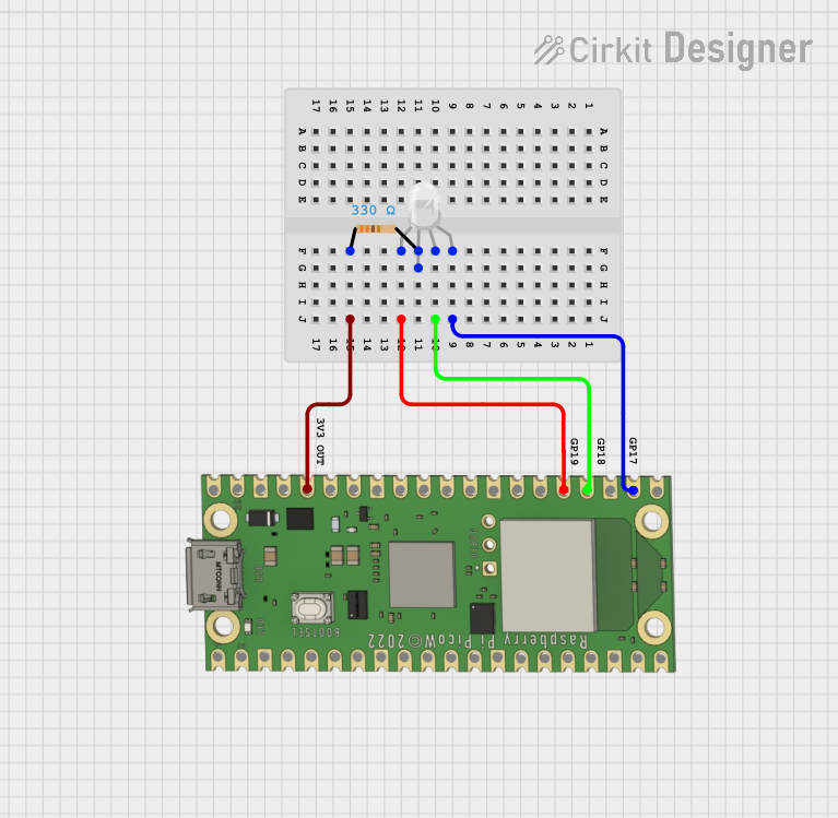 Open Project in Cirkit Designer
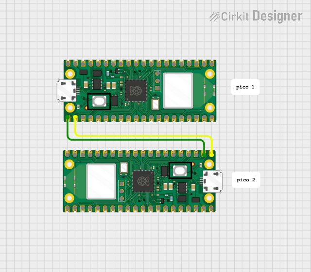 Open Project in Cirkit Designer
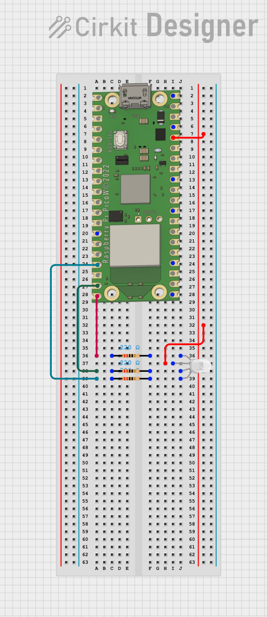 Open Project in Cirkit Designer
Explore Projects Built with Raspberry Pi Pico 2 W
Open Project in Cirkit DesignerOpen Project in Cirkit DesignerOpen Project in Cirkit DesignerOpen Project in Cirkit DesignerCommon Applications and Use Cases
- IoT devices and smart home automation
- Wireless sensor networks
- Robotics and motor control
- Data logging and environmental monitoring
- Prototyping and educational projects
Technical Specifications
Below are the key technical details of the Raspberry Pi Pico 2 W:
| Specification | Details |
|---|---|
| Processor | Dual-core ARM Cortex-M0+ |
| Clock Speed | Up to 133 MHz |
| Flash Memory | 2MB |
| RAM | 264KB SRAM |
| Connectivity | Built-in Wi-Fi (802.11n, 2.4 GHz) |
| GPIO Pins | 26 multi-function GPIO pins |
| Communication Interfaces | UART, SPI, I2C, PWM, ADC |
| Operating Voltage | 3.3V (logic level) |
| Input Voltage Range | 1.8V to 5.5V |
| USB Interface | USB 1.1 with host and device support |
| Dimensions | 51mm x 21mm |
| Power Consumption | Low power consumption, suitable for battery-powered applications |
Pin Configuration and Descriptions
The Raspberry Pi Pico 2 W has a total of 40 pins, including power, ground, GPIO, and communication pins. Below is the pinout description:
| Pin Number | Pin Name | Description |
|---|---|---|
| 1 | GP0 | General-purpose I/O, supports UART0 TX, I2C0 SDA, SPI0 RX |
| 2 | GP1 | General-purpose I/O, supports UART0 RX, I2C0 SCL, SPI0 CSn |
| 3 | GND | Ground |
| 4 | GP2 | General-purpose I/O, supports UART1 TX, I2C1 SDA, SPI0 SCK |
| 5 | GP3 | General-purpose I/O, supports UART1 RX, I2C1 SCL, SPI0 TX |
| ... | ... | ... (Refer to the official datasheet for the full pinout) |
| 39 | 3V3_EN | Enable 3.3V regulator |
| 40 | VSYS | Main system input voltage (1.8V to 5.5V) |
Usage Instructions
How to Use the Raspberry Pi Pico 2 W in a Circuit
Powering the Board:
- The board can be powered via the USB micro-B port or through the VSYS pin (1.8V to 5.5V).
- Ensure the power supply is stable and within the specified voltage range.
Connecting to Wi-Fi:
- Use the built-in Wi-Fi module to connect to a wireless network.
- The MicroPython or C/C++ SDK can be used to configure and manage Wi-Fi connections.
Programming the Board:
- The Raspberry Pi Pico 2 W supports programming in MicroPython, C, or C++.
- To upload code, connect the board to your computer via USB, hold the BOOTSEL button, and drag-and-drop the firmware file onto the mounted drive.
GPIO Usage:
- Configure GPIO pins as input or output using the appropriate libraries.
- Be mindful of the 3.3V logic level to avoid damaging the board.
Example: Blinking an LED with MicroPython
Below is an example of how to blink an LED connected to GPIO pin 15 using MicroPython:
Import the Pin and Timer classes from the machine module
from machine import Pin, Timer
Configure GPIO15 as an output pin
led = Pin(15, Pin.OUT)
Define a function to toggle the LED state
def toggle_led(timer): led.toggle() # Toggle the LED on/off
Create a timer to call the toggle_led function every 500ms
timer = Timer() timer.init(freq=2, mode=Timer.PERIODIC, callback=toggle_led)
Important Considerations and Best Practices
- Voltage Levels: Ensure all connected devices operate at 3.3V logic levels. Use level shifters if interfacing with 5V devices.
- Wi-Fi Antenna: Avoid placing metallic objects near the onboard antenna to maintain optimal Wi-Fi performance.
- Firmware Updates: Regularly check for firmware updates to ensure compatibility and access to the latest features.
Troubleshooting and FAQs
Common Issues and Solutions
The board is not detected by the computer:
- Ensure the USB cable is data-capable (not charge-only).
- Hold the BOOTSEL button while connecting the board to force it into USB mass storage mode.
Wi-Fi connection fails:
- Verify the SSID and password are correct.
- Check for interference or weak signal strength.
- Ensure the Wi-Fi network operates on the 2.4 GHz band (not 5 GHz).
GPIO pins not working as expected:
- Double-check the pin configuration in your code.
- Ensure no conflicting peripherals are using the same pins.
FAQs
Q: Can I use the Raspberry Pi Pico 2 W with Arduino IDE?
A: No, the Raspberry Pi Pico 2 W is not natively supported by the Arduino IDE. Use MicroPython or the C/C++ SDK instead.
Q: How do I reset the board to factory settings?
A: Reflash the firmware by holding the BOOTSEL button while connecting the board to your computer, then upload the original firmware file.
Q: What is the maximum Wi-Fi range?
A: The range depends on environmental factors but typically extends up to 30 meters indoors and 100 meters outdoors.
For additional support, refer to the official Raspberry Pi Pico 2 W datasheet and documentation.