Cirkit Designer Logo
Cirkit Designer
Your all-in-one circuit design IDE
Home / 
Component Documentation

How to Use SparkFun microB USB Breakout: Examples, Pinouts, and Specs

Image of SparkFun microB USB Breakout
Cirkit Designer LogoDesign with SparkFun microB USB Breakout in Cirkit Designer

Introduction

The SparkFun microB USB Breakout is a compact and versatile board designed to integrate USB connectivity into your projects. It features a microB USB connector, which is commonly used in many smartphones and portable devices. This breakout board is particularly useful for providing power to a project or for connecting it to a computer for data transfer.

Explore Projects Built with SparkFun microB USB Breakout

Use Cirkit Designer to design, explore, and prototype these projects online. Some projects support real-time simulation. Click "Open Project" to start designing instantly!
ESP32 CAM Wi-Fi Enabled Camera Module with USB Power
Image of abc: A project utilizing SparkFun microB USB Breakout in a practical application
This circuit consists of an ESP32 CAM module powered by a Micro USB breakout board. The USB breakout board supplies 5V and ground to the ESP32 CAM, enabling it to function and perform tasks such as image capture and processing.
Cirkit Designer LogoOpen Project in Cirkit Designer
Bluetooth-Controlled Robotic Vehicle with Ultrasonic Obstacle Detection and Motion Sensing
Image of 아두이노 드론: A project utilizing SparkFun microB USB Breakout in a practical application
This circuit features a SparkFun Pro Micro microcontroller interfaced with an L298N DC motor driver to control two DC motors, an HC-SR04 ultrasonic sensor for distance measurement, a Bluetooth module HM-10 for wireless communication, and an MPU-6050 for motion tracking. The Pro Micro is responsible for processing sensor data and managing motor speeds and directions via the motor driver. Power is supplied by a 5V battery connected to the Pro Micro and a separate battery case providing 12V to the motor driver.
Cirkit Designer LogoOpen Project in Cirkit Designer
ESP32-CAM and IR Sensor Interface with USB UART Communication
Image of esp32cam parking: A project utilizing SparkFun microB USB Breakout in a practical application
This circuit features an ESP32 CAM module interfaced with an IR sensor and a SparkFun USB UART Breakout board. The ESP32 CAM provides power to the IR sensor and receives its output signal, likely for processing or triggering camera actions based on IR detection. The USB UART Breakout board is connected to the ESP32 CAM for serial communication, enabling programming, debugging, or data exchange with a computer.
Cirkit Designer LogoOpen Project in Cirkit Designer
USB-Powered LED Indicator with NPN Transistor Control
Image of UAS: A project utilizing SparkFun microB USB Breakout in a practical application
This circuit is a simple LED driver powered via a Micro USB breakout board. It uses an NPN transistor to control the illumination of a red and a green LED, with current-limiting resistors in place to protect the LEDs.
Cirkit Designer LogoOpen Project in Cirkit Designer

Explore Projects Built with SparkFun microB USB Breakout

Use Cirkit Designer to design, explore, and prototype these projects online. Some projects support real-time simulation. Click "Open Project" to start designing instantly!
Image of abc: A project utilizing SparkFun microB USB Breakout in a practical application
ESP32 CAM Wi-Fi Enabled Camera Module with USB Power
This circuit consists of an ESP32 CAM module powered by a Micro USB breakout board. The USB breakout board supplies 5V and ground to the ESP32 CAM, enabling it to function and perform tasks such as image capture and processing.
Cirkit Designer LogoOpen Project in Cirkit Designer
Image of 아두이노 드론: A project utilizing SparkFun microB USB Breakout in a practical application
Bluetooth-Controlled Robotic Vehicle with Ultrasonic Obstacle Detection and Motion Sensing
This circuit features a SparkFun Pro Micro microcontroller interfaced with an L298N DC motor driver to control two DC motors, an HC-SR04 ultrasonic sensor for distance measurement, a Bluetooth module HM-10 for wireless communication, and an MPU-6050 for motion tracking. The Pro Micro is responsible for processing sensor data and managing motor speeds and directions via the motor driver. Power is supplied by a 5V battery connected to the Pro Micro and a separate battery case providing 12V to the motor driver.
Cirkit Designer LogoOpen Project in Cirkit Designer
Image of esp32cam parking: A project utilizing SparkFun microB USB Breakout in a practical application
ESP32-CAM and IR Sensor Interface with USB UART Communication
This circuit features an ESP32 CAM module interfaced with an IR sensor and a SparkFun USB UART Breakout board. The ESP32 CAM provides power to the IR sensor and receives its output signal, likely for processing or triggering camera actions based on IR detection. The USB UART Breakout board is connected to the ESP32 CAM for serial communication, enabling programming, debugging, or data exchange with a computer.
Cirkit Designer LogoOpen Project in Cirkit Designer
Image of UAS: A project utilizing SparkFun microB USB Breakout in a practical application
USB-Powered LED Indicator with NPN Transistor Control
This circuit is a simple LED driver powered via a Micro USB breakout board. It uses an NPN transistor to control the illumination of a red and a green LED, with current-limiting resistors in place to protect the LEDs.
Cirkit Designer LogoOpen Project in Cirkit Designer

Common Applications and Use Cases

  • Powering microcontroller boards via USB
  • Data transfer between a device and a computer
  • Prototyping USB devices
  • Adding a USB interface to custom electronics
  • Charging battery-powered projects

Technical Specifications

Key Technical Details

  • Voltage Rating: 5V (typical USB supply voltage)
  • Current Rating: Up to 500mA for USB 2.0
  • Connector Type: microB USB

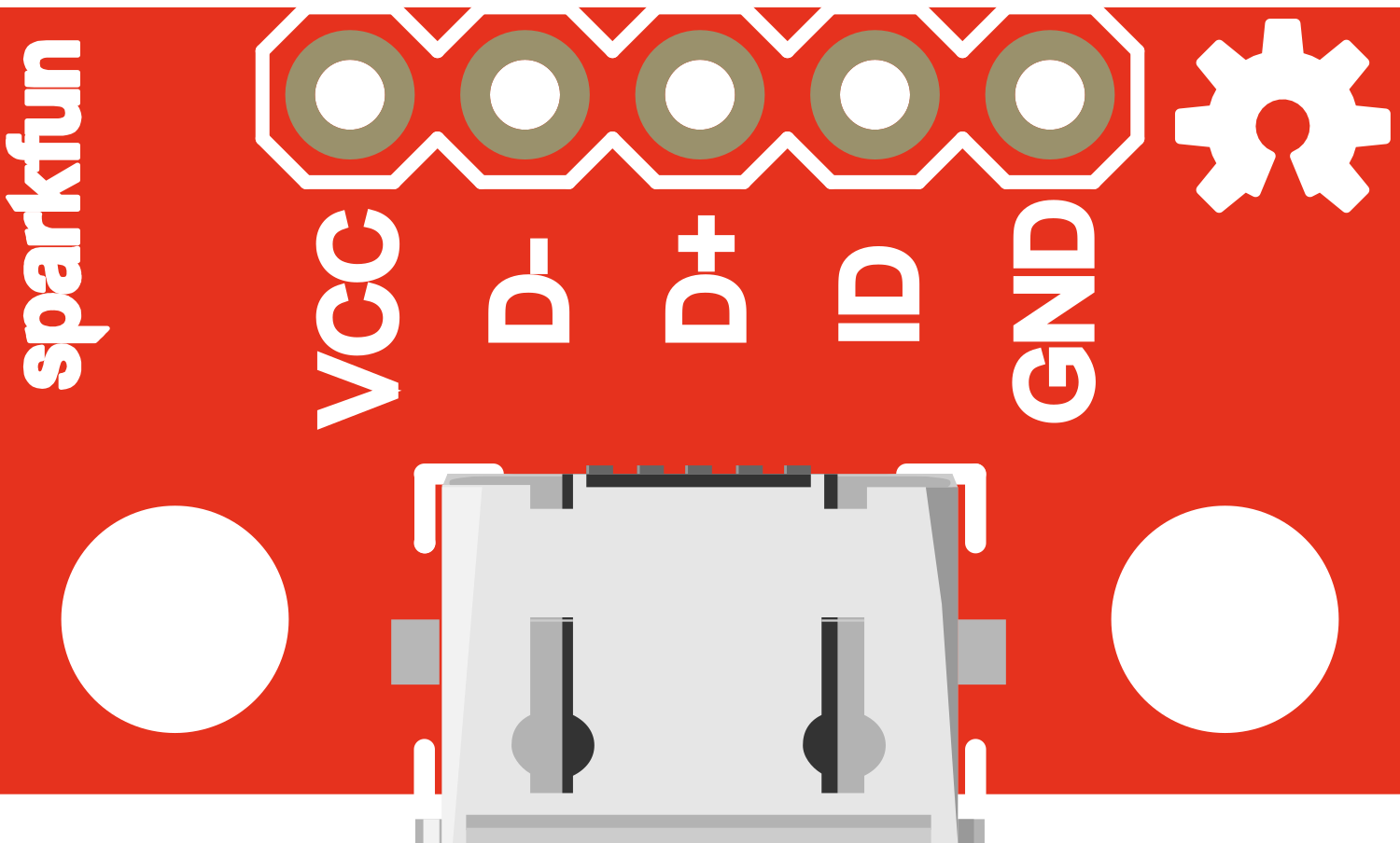
Pin Configuration and Descriptions

Pin Number Name Description
1 VBUS Provides 5V from the USB connection
2 D- Data minus, USB data line
3 D+ Data plus, USB data line
4 ID Identification pin, typically not connected
5 GND Ground connection

Usage Instructions

How to Use the Component in a Circuit

  1. Soldering: Begin by soldering the provided header pins or wires directly to the breakout board's through-holes.
  2. Power Connection: Connect the VBUS pin to the 5V power input on your circuit and the GND pin to the common ground.
  3. Data Transfer: If data transfer is required, connect the D+ and D- pins to the appropriate data lines on your microcontroller or USB interface chip.

Important Considerations and Best Practices

  • Voltage Regulation: Ensure that your circuit can handle the 5V supply voltage. If not, use a voltage regulator to step down the voltage to an appropriate level.
  • Current Limitation: Do not exceed the 500mA current rating. If your project requires more current, consider using a powered USB hub.
  • Data Lines: For data transfer applications, ensure that the D+ and D- lines are connected correctly and that any required resistors or matching impedances are in place.
  • USB Standards Compliance: If designing a USB device, ensure compliance with USB standards for signaling and power management.

Example Code for Arduino UNO

// This example demonstrates how to power an Arduino UNO using the SparkFun microB USB Breakout.

void setup() {
  // Initialize the Serial interface at 9600 baud rate for debugging.
  Serial.begin(9600);
}

void loop() {
  // Send a message to the Serial Monitor every second.
  Serial.println("Arduino is powered via SparkFun microB USB Breakout!");
  delay(1000); // Wait for 1000 milliseconds (1 second).
}

Troubleshooting and FAQs

Common Issues

  • Power Not Working: Ensure that the VBUS and GND pins are properly soldered and that there are no short circuits.
  • Data Transfer Not Working: Check the D+ and D- connections, and ensure that the microcontroller's USB interface is configured correctly.

Solutions and Tips for Troubleshooting

  • Check Connections: Use a multimeter to verify that all connections are secure and that there is continuity where expected.
  • Inspect for Shorts: Look for any solder bridges or debris that might cause a short circuit between the breakout board pins.
  • USB Cable: Ensure that the microB USB cable used is functional and not damaged.

FAQs

Q: Can I use this breakout to charge a battery? A: Yes, but ensure that the charging circuit is designed to handle the 5V input and that it does not draw more than 500mA.

Q: Is it possible to use this breakout for USB OTG (On-The-Go)? A: The ID pin is not connected on this breakout, which is typically used for OTG identification. Therefore, it is not suitable for OTG applications without modification.

Q: Can I use this breakout board for USB 3.0 devices? A: This breakout is designed for USB 2.0 connections and does not support the additional data lines used in USB 3.0.