How to Use Output Instrumentation Amplifier: Examples, Pinouts, and Specs
Introduction
The AD8226 is a high-performance instrumentation amplifier manufactured by Analog Devices. It is designed to amplify low-level differential signals while rejecting common-mode noise and interference. This makes it ideal for applications requiring precise and accurate signal amplification, such as sensor interfacing, medical instrumentation, and data acquisition systems.
Explore Projects Built with Output Instrumentation Amplifier

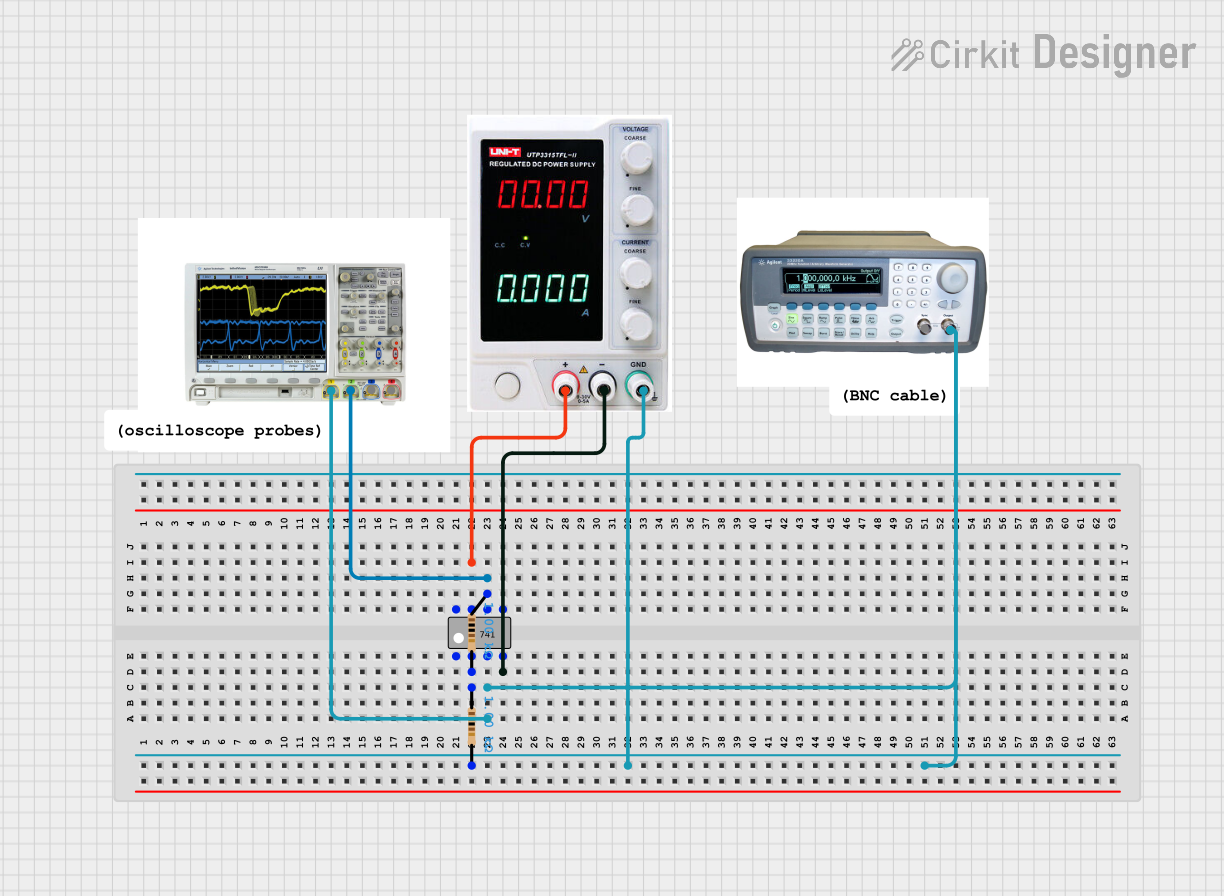
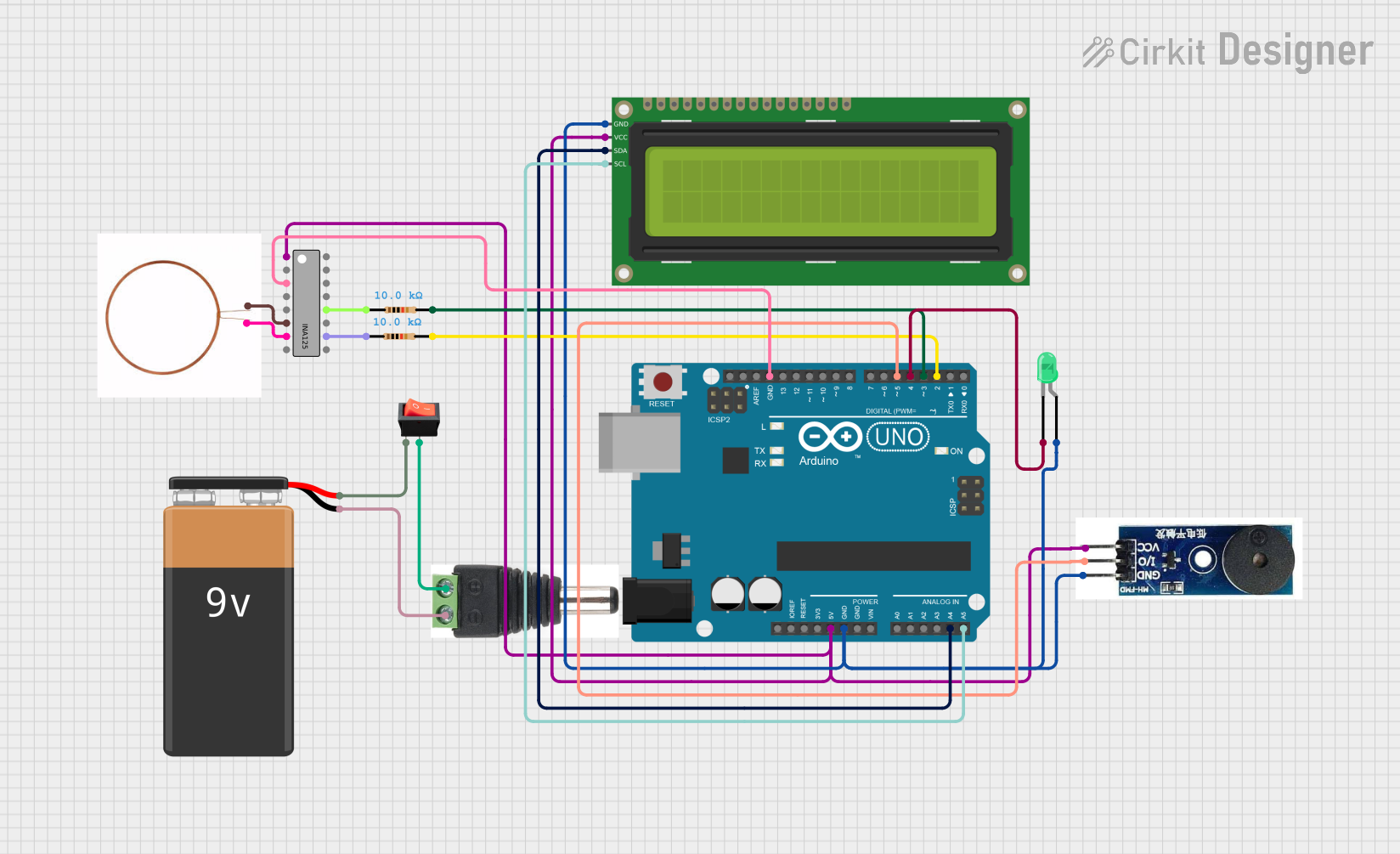
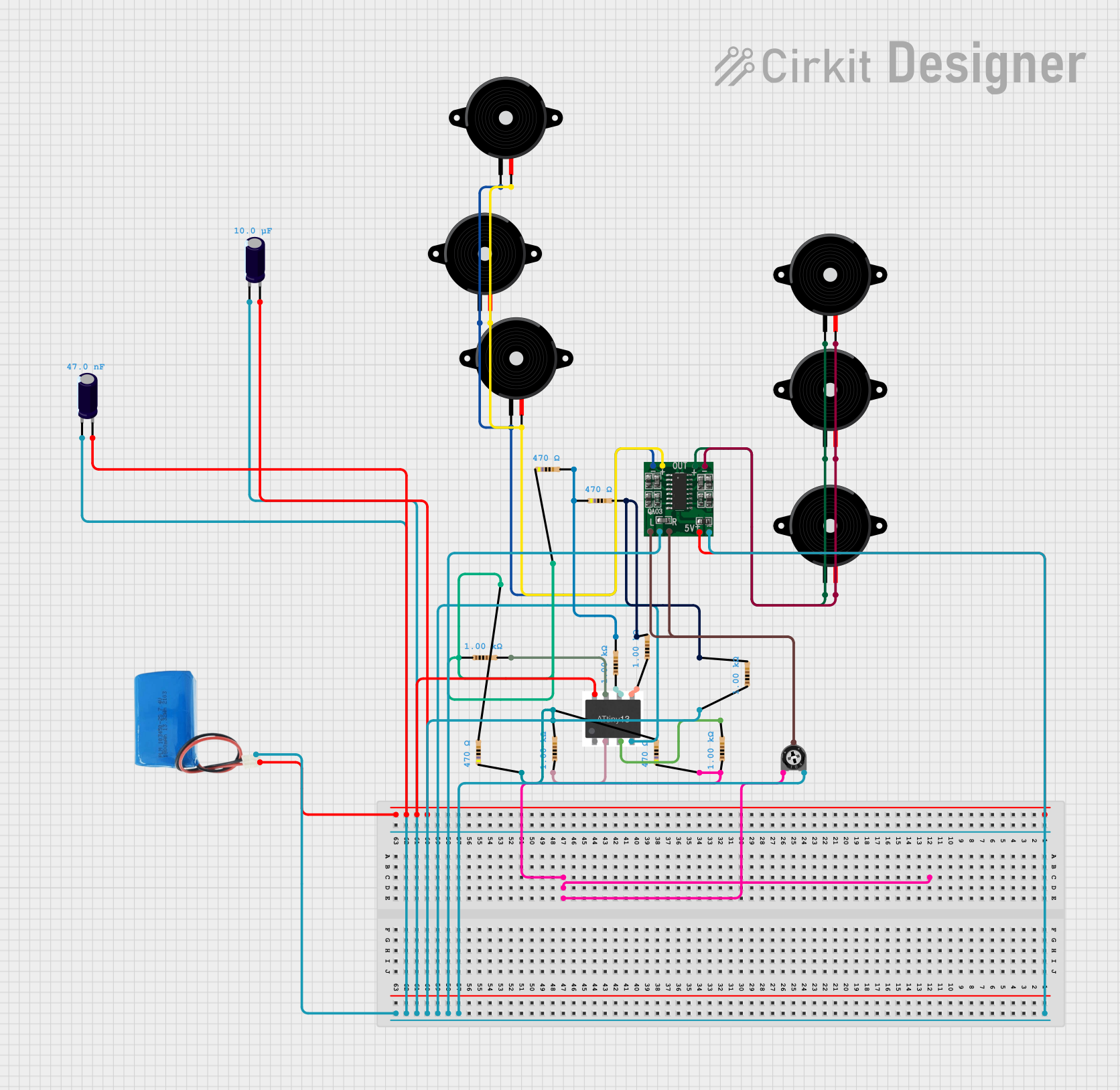
Explore Projects Built with Output Instrumentation Amplifier
Common Applications and Use Cases
- Sensor signal conditioning (e.g., thermocouples, strain gauges, and pressure sensors)
- Medical instrumentation (e.g., ECG, EEG, and blood pressure monitors)
- Data acquisition systems
- Industrial process controls
- Precision measurement systems
Technical Specifications
The AD8226 offers excellent performance and flexibility, making it suitable for a wide range of applications. Below are its key technical specifications:
Key Technical Details
| Parameter | Value |
|---|---|
| Supply Voltage Range | ±2.3 V to ±18 V or 2.3 V to 36 V |
| Input Voltage Range | -Vs + 0.1 V to +Vs - 1.2 V |
| Gain Range | 1 to 1000 (set by external resistor) |
| Gain Error | ±0.3% (maximum) |
| Common-Mode Rejection Ratio (CMRR) | 80 dB (minimum) at G = 1 |
| Input Offset Voltage | ±200 µV (maximum) |
| Input Bias Current | 1 nA (typical) |
| Bandwidth | 1.5 MHz at G = 1 |
| Slew Rate | 0.3 V/µs |
| Operating Temperature Range | -40°C to +125°C |
| Package Options | 8-lead SOIC, 8-lead MSOP |
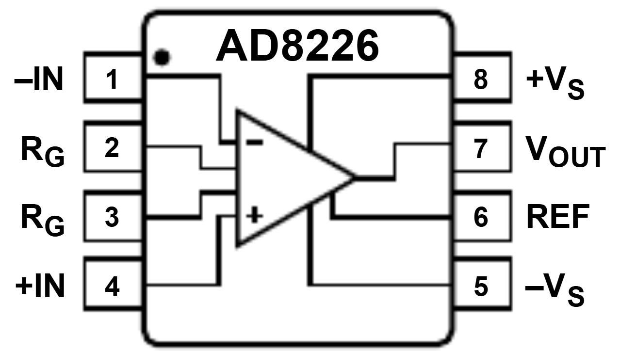
Pin Configuration and Descriptions
The AD8226 is available in an 8-pin package. Below is the pinout and description:
| Pin Number | Pin Name | Description |
|---|---|---|
| 1 | REF | Reference voltage input. Sets the output voltage reference. |
| 2 | -IN | Inverting input of the amplifier. |
| 3 | +IN | Non-inverting input of the amplifier. |
| 4 | -Vs | Negative power supply. |
| 5 | RG | Gain resistor connection. Sets the gain. |
| 6 | RG | Gain resistor connection. Sets the gain. |
| 7 | OUT | Amplifier output. |
| 8 | +Vs | Positive power supply. |
Usage Instructions
The AD8226 is straightforward to use in a circuit. Below are the steps and considerations for proper usage:
How to Use the Component in a Circuit
- Power Supply: Connect the positive supply voltage to the
+Vspin and the negative supply voltage to the-Vspin. Ensure the supply voltage is within the specified range (±2.3 V to ±18 V or 2.3 V to 36 V). - Input Signal: Connect the differential input signal to the
+INand-INpins. Ensure the input voltage is within the specified range. - Gain Setting: Use an external resistor between the two
RGpins to set the desired gain. The gain is calculated as: [ G = 1 + \frac{49.4 , \text{k}\Omega}{R_G} ] where ( R_G ) is the resistance in ohms. - Reference Voltage: Connect the
REFpin to a reference voltage source. This sets the output voltage reference. For single-supply operation, connectREFto mid-supply (e.g., ( V_{REF} = \frac{+Vs}{2} )). - Output Signal: The amplified signal is available at the
OUTpin. Ensure the load connected to the output does not exceed the amplifier's drive capability.
Important Considerations and Best Practices
- Input Impedance: The AD8226 has high input impedance, making it suitable for interfacing with high-impedance sensors.
- Power Supply Decoupling: Use decoupling capacitors (e.g., 0.1 µF and 10 µF) close to the power supply pins to reduce noise and ensure stable operation.
- Gain Resistor Selection: Use precision resistors for ( R_G ) to minimize gain error and improve accuracy.
- Thermal Management: Ensure the device operates within the specified temperature range to avoid performance degradation.
Example: Connecting to an Arduino UNO
The AD8226 can be used with an Arduino UNO to amplify sensor signals. Below is an example of interfacing the amplifier with a thermocouple sensor:
Circuit Connections
- Connect the thermocouple's differential output to the
+INand-INpins of the AD8226. - Set the gain using an appropriate resistor between the
RGpins. - Connect the
OUTpin of the AD8226 to an analog input pin (e.g., A0) of the Arduino UNO. - Power the AD8226 using the Arduino's 5V and GND pins.
Arduino Code
// Example code to read amplified signal from AD8226 and display it on the serial monitor

const int analogPin = A0; // Analog pin connected to AD8226 OUT pin
float voltage = 0.0;      // Variable to store the measured voltage
float Vref = 5.0;         // Reference voltage of Arduino UNO (5V)

void setup() {
  Serial.begin(9600); // Initialize serial communication at 9600 baud
}

void loop() {
  int sensorValue = analogRead(analogPin); // Read the analog input
  voltage = (sensorValue / 1023.0) * Vref; // Convert ADC value to voltage

  // Print the measured voltage to the serial monitor
  Serial.print("Measured Voltage: ");
  Serial.print(voltage, 3); // Print voltage with 3 decimal places
  Serial.println(" V");

  delay(500); // Wait for 500 ms before the next reading
}
Troubleshooting and FAQs
Common Issues and Solutions
No Output Signal:
- Verify the power supply connections and ensure the supply voltage is within the specified range.
- Check the input signal connections and ensure the signal is within the input voltage range.
- Ensure the gain resistor is properly connected and has the correct value.
Output Signal Saturation:
- Ensure the input signal is not too large for the selected gain.
- Verify the reference voltage at the
REFpin is correctly set.
Excessive Noise in Output:
- Use proper shielding and grounding techniques to minimize noise.
- Add decoupling capacitors near the power supply pins.
Incorrect Gain:
- Double-check the value of the gain resistor ( R_G ).
- Use precision resistors to minimize gain error.
FAQs
Q: Can the AD8226 operate with a single power supply?
A: Yes, the AD8226 can operate with a single supply voltage. In this case, connect the REF pin to mid-supply to ensure proper operation.
Q: What is the maximum gain I can achieve with the AD8226?
A: The maximum gain is 1000, which can be achieved by selecting an appropriate ( R_G ) value.
Q: How do I minimize offset voltage errors?
A: Use precision resistors for ( R_G ) and ensure the input signal is properly balanced to minimize offset errors.