How to Use Sensor Optocoupler Disk Speed: Examples, Pinouts, and Specs
Introduction
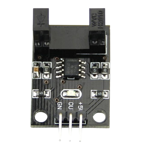
The Sensor Optocoupler Disk Speed is an optical sensor module designed to measure rotational speed or detect the position of a rotating disk. It uses an optocoupler, which consists of an infrared emitter and a photodetector, to detect interruptions caused by slots or holes in a rotating disk. This component is widely used in applications such as motor speed measurement, robotics, industrial automation, and tachometers.
By detecting the frequency of interruptions in the light beam, the Sensor Optocoupler Disk Speed can provide precise measurements of rotational speed or position.
Explore Projects Built with Sensor Optocoupler Disk Speed
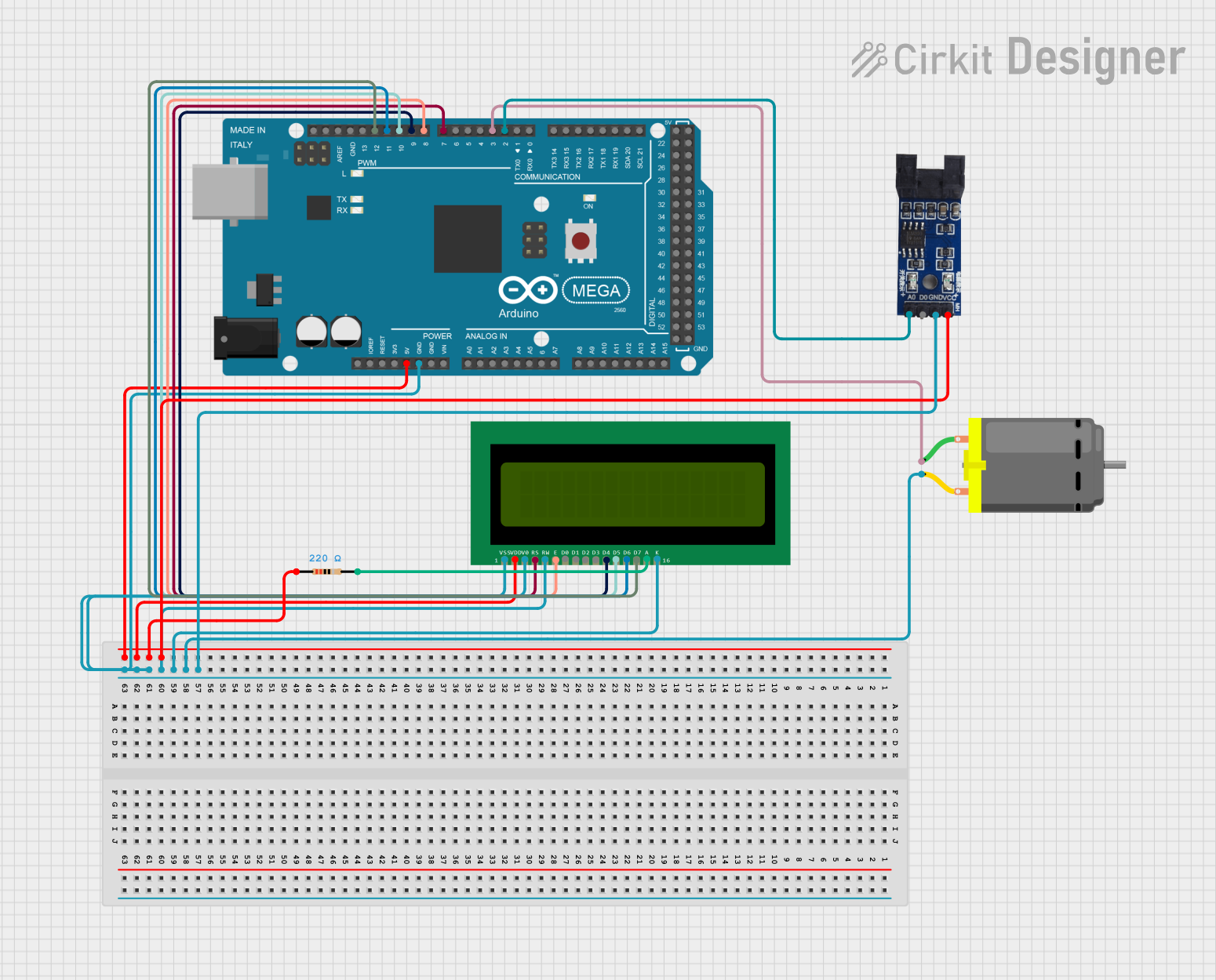
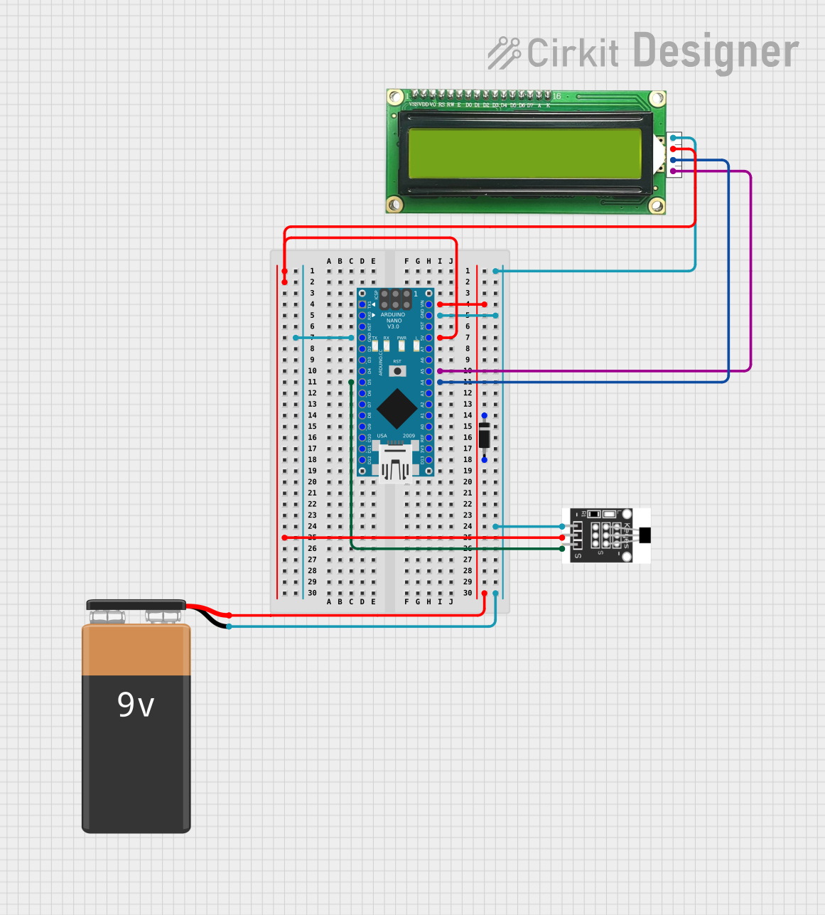
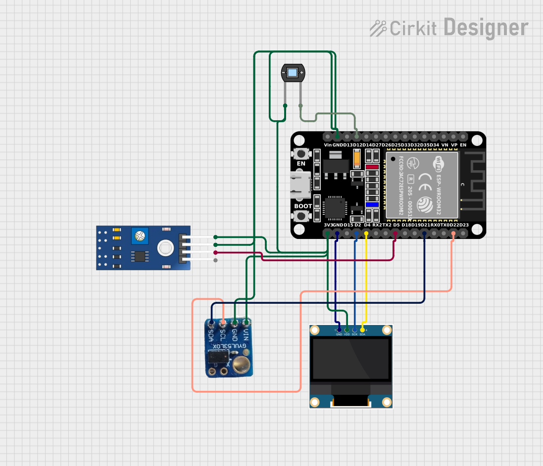
Explore Projects Built with Sensor Optocoupler Disk Speed
Technical Specifications
- Operating Voltage: 3.3V to 5V DC
- Output Type: Digital (High/Low)
- Detection Range: 0.5mm to 5mm (depending on the disk material and slot size)
- Response Time: < 10 µs
- Operating Temperature: -20°C to 70°C
- Dimensions: Typically 30mm x 15mm x 10mm (varies by manufacturer)
Pin Configuration and Descriptions
| Pin | Name | Description |
|---|---|---|
| 1 | VCC | Power supply input (3.3V to 5V DC) |
| 2 | GND | Ground connection |
| 3 | OUT | Digital output signal (High when no interruption, Low when the beam is blocked) |
Usage Instructions
How to Use the Component in a Circuit
Connect the Power Supply:
- Connect the VCC pin to a 3.3V or 5V DC power source.
- Connect the GND pin to the ground of the power source.
Connect the Output Signal:
- Connect the OUT pin to a digital input pin of a microcontroller (e.g., Arduino UNO).
- Use a pull-up resistor (e.g., 10kΩ) if required, depending on the microcontroller's input configuration.
Position the Sensor:
- Place the optocoupler module near the rotating disk, ensuring the slots or holes in the disk pass through the sensor's detection area.
- Maintain a gap of 0.5mm to 5mm between the sensor and the disk for optimal performance.
Read the Output:
- When the light beam is uninterrupted, the OUT pin will output a HIGH signal.
- When the beam is blocked by a slot or hole, the OUT pin will output a LOW signal.
Important Considerations and Best Practices
- Ensure the disk material is opaque to block the infrared light effectively.
- Avoid ambient light interference by using the sensor in a controlled environment or shielding it from external light sources.
- Use a stable power supply to prevent fluctuations in the sensor's performance.
- Calibrate the sensor's position to ensure accurate detection of the disk's slots or holes.
Example Code for Arduino UNO
// Example code to measure disk speed using the Sensor Optocoupler Disk Speed
// Connect the OUT pin of the sensor to Arduino digital pin 2

const int sensorPin = 2;  // Sensor output connected to digital pin 2
volatile int pulseCount = 0;  // Variable to store the number of pulses

void setup() {
  pinMode(sensorPin, INPUT);  // Set the sensor pin as input
  attachInterrupt(digitalPinToInterrupt(sensorPin), countPulse, FALLING);
  // Attach an interrupt to count pulses on falling edge of the signal

  Serial.begin(9600);  // Initialize serial communication
}

void loop() {
  delay(1000);  // Wait for 1 second
  Serial.print("Pulses in 1 second: ");
  Serial.println(pulseCount);  // Print the number of pulses
  pulseCount = 0;  // Reset the pulse count for the next interval
}

void countPulse() {
  pulseCount++;  // Increment the pulse count on each falling edge
}
Troubleshooting and FAQs
Common Issues and Solutions
No Output Signal:
- Cause: Incorrect wiring or loose connections.
- Solution: Double-check the wiring and ensure all connections are secure.
Inconsistent Readings:
- Cause: Ambient light interference or unstable power supply.
- Solution: Shield the sensor from external light and use a regulated power supply.
Sensor Not Detecting Slots:
- Cause: Improper alignment or disk material not blocking the infrared light.
- Solution: Adjust the sensor's position and ensure the disk material is opaque.
Output Always HIGH or LOW:
- Cause: Sensor damaged or incorrect gap between the sensor and disk.
- Solution: Verify the sensor's functionality and adjust the gap to the recommended range.
FAQs
Q: Can this sensor measure the speed of a transparent disk?
A: No, the disk must be opaque to block the infrared light effectively.Q: What is the maximum rotational speed this sensor can detect?
A: The sensor can detect speeds up to approximately 100,000 RPM, depending on the slot size and response time.Q: Can I use this sensor with a 12V power supply?
A: No, the sensor is designed to operate at 3.3V to 5V DC. Using a higher voltage may damage the component.Q: How do I calculate the rotational speed from the pulse count?
A: Measure the number of pulses in a fixed time interval (e.g., 1 second) and multiply by the number of slots on the disk to calculate the RPM.