How to Use Touch Sensor: Examples, Pinouts, and Specs
Introduction
A touch sensor detects physical touch or proximity, allowing for user interaction with electronic devices. It converts the touch input into an electrical signal, which can be used to trigger actions or control other components. Touch sensors are widely used in modern electronics, including smartphones, touchpads, home automation systems, and interactive displays. They provide a simple and intuitive way for users to interact with devices without the need for mechanical buttons.
Explore Projects Built with Touch Sensor

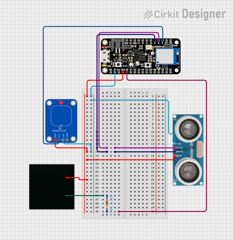
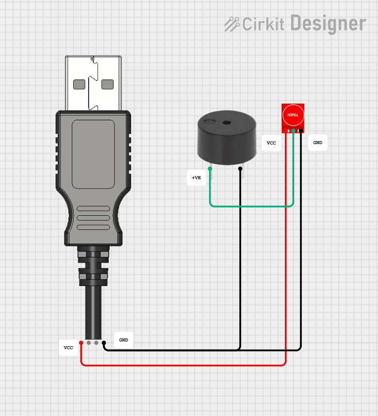
Explore Projects Built with Touch Sensor
Common Applications and Use Cases
- Capacitive touch buttons for home appliances
- Touch-sensitive light switches
- Interactive kiosks and displays
- Wearable devices and smartwatches
- Robotics and automation systems
- Gaming controllers and touchpads
Technical Specifications
Below are the general technical specifications for a typical capacitive touch sensor module, such as the TTP223-based module:
| Parameter | Specification |
|---|---|
| Operating Voltage | 2.0V to 5.5V |
| Operating Current | < 15 µA (standby), ~1.5 mA (active) |
| Response Time | ~60 ms (fast mode), ~220 ms (low power mode) |
| Output Type | Digital (High/Low) |
| Output Voltage (High) | ~Vcc |
| Output Voltage (Low) | ~0V |
| Touch Sensitivity | Adjustable (via onboard capacitor) |
| Operating Temperature | -30°C to 70°C |
| Dimensions | ~15mm x 11mm x 2mm |
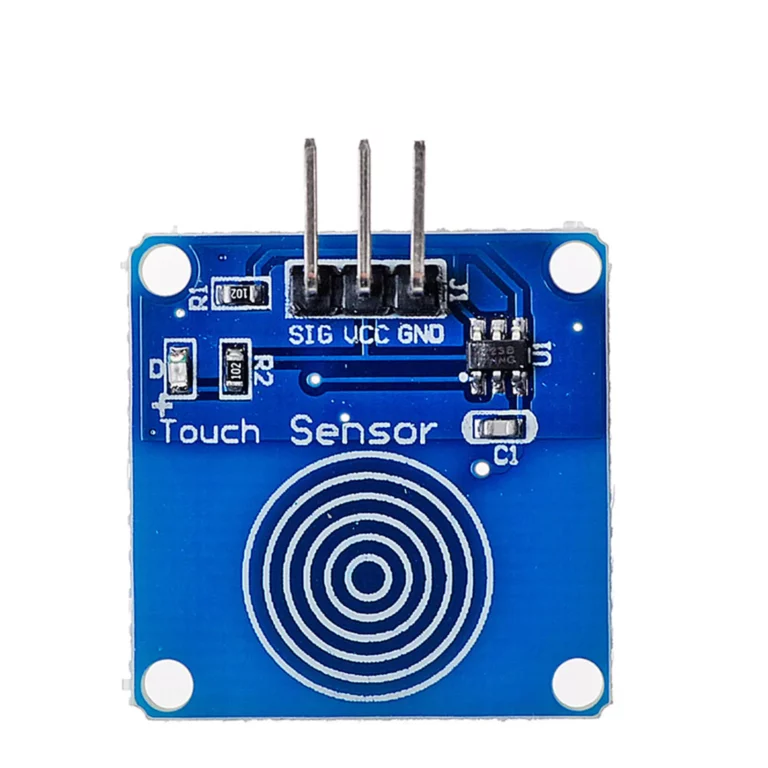
Pin Configuration and Descriptions
The touch sensor module typically has three pins:
| Pin | Name | Description |
|---|---|---|
| 1 | VCC | Power supply pin. Connect to a voltage source (2.0V to 5.5V). |
| 2 | GND | Ground pin. Connect to the ground of the circuit. |
| 3 | OUT | Digital output pin. Outputs HIGH when touched and LOW when not touched. |
Usage Instructions
How to Use the Touch Sensor in a Circuit
- Power the Sensor: Connect the
VCCpin to a 3.3V or 5V power source and theGNDpin to the ground. - Connect the Output: Connect the
OUTpin to a microcontroller input pin (e.g., Arduino digital pin) or directly to an LED or other device for testing. - Test the Sensor: When the sensor is touched, the
OUTpin will output a HIGH signal. When not touched, it will output a LOW signal.
Important Considerations and Best Practices
- Power Supply: Ensure the power supply voltage is within the specified range (2.0V to 5.5V) to avoid damaging the sensor.
- Debouncing: If the sensor is used for triggering events, consider implementing software debouncing to avoid false triggers.
- Sensitivity Adjustment: Some touch sensors allow sensitivity adjustment by changing the onboard capacitor. Refer to the sensor's datasheet for details.
- Avoid Interference: Keep the sensor away from high-frequency noise sources or strong electromagnetic fields to ensure reliable operation.
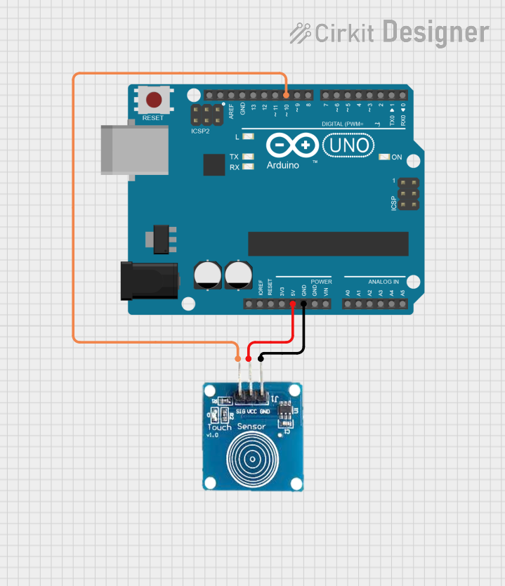
Example: Using the Touch Sensor with Arduino UNO
Below is an example of how to connect and program the touch sensor with an Arduino UNO:
Circuit Diagram
- Connect the
VCCpin of the touch sensor to the 5V pin on the Arduino. - Connect the
GNDpin of the touch sensor to the GND pin on the Arduino. - Connect the
OUTpin of the touch sensor to digital pin 7 on the Arduino.
Arduino Code
// Define the pin connected to the touch sensor output
const int touchSensorPin = 7;

// Define the pin connected to an LED (optional)
const int ledPin = 13;

void setup() {
  pinMode(touchSensorPin, INPUT); // Set the touch sensor pin as input
  pinMode(ledPin, OUTPUT);        // Set the LED pin as output
  Serial.begin(9600);             // Initialize serial communication
}

void loop() {
  // Read the state of the touch sensor
  int touchState = digitalRead(touchSensorPin);

  if (touchState == HIGH) {
    // If the sensor is touched, turn on the LED and print a message
    digitalWrite(ledPin, HIGH);
    Serial.println("Touch detected!");
  } else {
    // If the sensor is not touched, turn off the LED
    digitalWrite(ledPin, LOW);
  }

  delay(100); // Small delay to stabilize readings
}
Troubleshooting and FAQs
Common Issues and Solutions
Sensor Not Responding
- Cause: Incorrect wiring or insufficient power supply.
- Solution: Double-check the connections and ensure the power supply voltage is within the specified range.
False Triggers
- Cause: Electrical noise or interference from nearby components.
- Solution: Use proper grounding and shielding. Add a capacitor (e.g., 0.1 µF) across the power supply pins to filter noise.
Low Sensitivity
- Cause: Sensor sensitivity is not properly adjusted.
- Solution: Adjust the onboard capacitor (if available) or ensure the sensor surface is clean and unobstructed.
Output Stuck HIGH or LOW
- Cause: Faulty sensor or damaged module.
- Solution: Replace the sensor module and test again.
FAQs
Q1: Can the touch sensor detect proximity without physical contact?
A1: Yes, capacitive touch sensors can detect proximity, but the range is typically limited to a few millimeters.
Q2: Can I use multiple touch sensors in the same circuit?
A2: Yes, you can use multiple sensors, but ensure each sensor has a unique connection to the microcontroller.
Q3: Is the touch sensor waterproof?
A3: Most touch sensors are not waterproof. If water resistance is required, consider using a sealed enclosure or a specialized waterproof sensor.
Q4: Can the sensor work with a 3.3V microcontroller?
A4: Yes, the sensor operates within a voltage range of 2.0V to 5.5V, making it compatible with 3.3V systems.