How to Use ESP32-S3-Touch-LCD-4inch 480x480: Examples, Pinouts, and Specs
Introduction
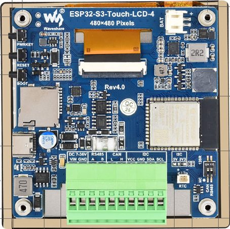
The ESP32-S3-Touch-LCD-4inch 480x480 by Waveshare (Part ID: ESP32-S3-Touch-LCD-4) is a versatile 4-inch touchscreen display module with a resolution of 480x480 pixels. It integrates the powerful ESP32-S3 microcontroller, which features dual-core processing, Wi-Fi, and Bluetooth connectivity. This component is ideal for creating interactive applications, IoT projects, and graphical user interfaces (GUIs). Its compact design and rich feature set make it suitable for both hobbyists and professional developers.
Explore Projects Built with ESP32-S3-Touch-LCD-4inch 480x480


Explore Projects Built with ESP32-S3-Touch-LCD-4inch 480x480
Common Applications and Use Cases
- Smart home control panels
- IoT dashboards and monitoring systems
- Portable devices with touch-based interfaces
- Educational and prototyping projects
- Industrial control systems
- Wearable devices with graphical displays
Technical Specifications
Key Technical Details
| Parameter | Specification |
|---|---|
| Display Size | 4 inches |
| Resolution | 480x480 pixels |
| Touchscreen Type | Capacitive |
| Microcontroller | ESP32-S3 |
| Processor | Dual-core Xtensa LX7 |
| Connectivity | Wi-Fi 802.11 b/g/n, Bluetooth 5.0 |
| Flash Memory | 16 MB |
| PSRAM | 8 MB |
| Operating Voltage | 5V (via USB-C) |
| Communication Interfaces | SPI, I2C, UART |
| GPIO Pins | 20 (available for user applications) |
| Dimensions | 85.6mm x 67.2mm x 12.5mm |
Pin Configuration and Descriptions
The ESP32-S3-Touch-LCD-4inch module features a USB-C port for power and programming, as well as a GPIO header for external connections. Below is the pin configuration:
| Pin Name | Function | Description |
|---|---|---|
| 3V3 | Power Output | 3.3V output for external peripherals |
| GND | Ground | Common ground |
| GPIO0 | Boot Mode Selection | Used for flashing firmware |
| GPIO1 | UART TX | Transmit data for UART communication |
| GPIO3 | UART RX | Receive data for UART communication |
| GPIO4 | General Purpose I/O | Configurable GPIO pin |
| GPIO5 | General Purpose I/O | Configurable GPIO pin |
| GPIO18 | SPI Clock (SCK) | SPI clock signal |
| GPIO19 | SPI Master Out (MOSI) | SPI data output |
| GPIO21 | I2C Data (SDA) | I2C data line |
| GPIO22 | I2C Clock (SCL) | I2C clock line |
| GPIO25 | Touch Interrupt | Interrupt signal from the touchscreen controller |
| GPIO26 | Backlight Control (PWM) | Controls the display backlight brightness |
Usage Instructions
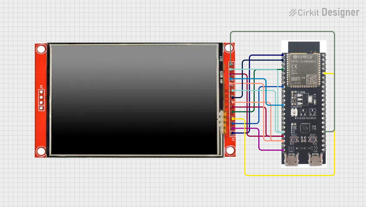
How to Use the Component in a Circuit
- Powering the Module: Connect the module to a 5V power source using the USB-C port. Alternatively, you can power it via the 3V3 and GND pins if using an external power supply.
- Programming the ESP32-S3: Use the USB-C port to connect the module to your computer. Install the necessary drivers and use the Arduino IDE or ESP-IDF for programming.
- Connecting Peripherals: Use the GPIO pins to connect sensors, actuators, or other peripherals. Ensure that the voltage levels are compatible with the ESP32-S3 (3.3V logic).
- Touchscreen Interface: The capacitive touchscreen can be used to create interactive GUIs. Libraries such as LVGL (Light and Versatile Graphics Library) are recommended for GUI development.
Important Considerations and Best Practices
- Voltage Levels: Ensure that all connected peripherals operate at 3.3V logic levels to avoid damaging the GPIO pins.
- Firmware Updates: Regularly update the firmware to ensure compatibility with the latest features and bug fixes.
- Heat Management: While the ESP32-S3 is efficient, prolonged operation at high loads may generate heat. Ensure proper ventilation if used in enclosed spaces.
- Touchscreen Calibration: Some applications may require touchscreen calibration for accurate input detection. Use the provided libraries or tools for this purpose.
Example Code for Arduino UNO Integration
Below is an example of how to display text on the touchscreen using the Arduino IDE and the LVGL library:
#include <lvgl.h>
#include <TFT_eSPI.h>

// Initialize the display and touch drivers
TFT_eSPI tft = TFT_eSPI();
lv_disp_draw_buf_t draw_buf;
lv_color_t buf[LV_HOR_RES_MAX * 10];

// Function to initialize LVGL
void lvgl_setup() {
  lv_init();
  tft.begin(); // Initialize the display
  tft.setRotation(1); // Set display orientation

  lv_disp_draw_buf_init(&draw_buf, buf, NULL, LV_HOR_RES_MAX * 10);

  static lv_disp_drv_t disp_drv;
  lv_disp_drv_init(&disp_drv);
  disp_drv.hor_res = 480; // Horizontal resolution
  disp_drv.ver_res = 480; // Vertical resolution
  disp_drv.flush_cb = my_disp_flush; // Display flush callback
  disp_drv.draw_buf = &draw_buf;
  lv_disp_drv_register(&disp_drv);
}

// Callback function to flush the display buffer
void my_disp_flush(lv_disp_drv_t *disp, const lv_area_t *area, lv_color_t *color_p) {
  uint16_t c;
  tft.startWrite();
  tft.setAddrWindow(area->x1, area->y1, area->x2 - area->x1 + 1, area->y2 - area->y1 + 1);
  for (int y = area->y1; y <= area->y2; y++) {
    for (int x = area->x1; x <= area->x2; x++) {
      c = color_p->full;
      tft.pushColor(c);
      color_p++;
    }
  }
  tft.endWrite();
  lv_disp_flush_ready(disp);
}

void setup() {
  lvgl_setup(); // Initialize LVGL
  lv_obj_t *label = lv_label_create(lv_scr_act()); // Create a label
  lv_label_set_text(label, "Hello, ESP32-S3!"); // Set label text
  lv_obj_align(label, LV_ALIGN_CENTER, 0, 0); // Center the label
}

void loop() {
  lv_timer_handler(); // Handle LVGL tasks
  delay(5);
}
Troubleshooting and FAQs
Common Issues Users Might Face
Display Not Turning On:
- Ensure the module is properly powered (5V via USB-C or 3V3 pin).
- Check the backlight control pin (GPIO26) for proper PWM signal.
Touchscreen Not Responding:
- Verify that the touchscreen interrupt pin (GPIO25) is correctly connected.
- Ensure the touchscreen driver is initialized in your code.
Wi-Fi or Bluetooth Connectivity Issues:
- Check your firmware for proper Wi-Fi/Bluetooth initialization.
- Ensure the antenna is not obstructed by metal enclosures.
Programming Errors:
- Ensure the correct board is selected in the Arduino IDE or ESP-IDF.
- Put the module in boot mode by holding GPIO0 low during reset.
Solutions and Tips for Troubleshooting
- Use a multimeter to verify power supply voltages.
- Check the serial monitor for error messages during programming.
- Update the Arduino IDE or ESP-IDF to the latest version for compatibility.
- Refer to the Waveshare documentation for additional support and resources.