How to Use Connector 3 In 6 Out: Examples, Pinouts, and Specs
Introduction
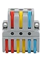
The Connector 3 In 6 Out is a versatile electronic component designed to distribute three input signals to six output channels. This component is particularly useful in circuits where multiple devices or modules need to receive the same signals simultaneously. It simplifies signal routing and reduces the need for complex wiring, making it an essential tool in prototyping, testing, and production environments.
Explore Projects Built with Connector 3 In 6 Out


Explore Projects Built with Connector 3 In 6 Out
Common Applications and Use Cases
- Signal distribution in audio, video, or data systems
- Prototyping circuits with multiple modules requiring the same input
- Parallel signal routing in microcontroller-based projects
- Splitting control signals for multiple actuators or sensors
- Simplifying wiring in complex electronic systems
Technical Specifications
The Connector 3 In 6 Out is a passive component that does not amplify or modify the signals passing through it. Below are its key technical details:
General Specifications
- Input Channels: 3
- Output Channels: 6 (2 outputs per input channel)
- Maximum Voltage Rating: 30V DC
- Maximum Current Rating: 2A per channel
- Connector Type: Screw terminal or pin header (varies by model)
- Operating Temperature Range: -20°C to 70°C
- Dimensions: 50mm x 30mm x 15mm (L x W x H)
Pin Configuration and Descriptions
The Connector 3 In 6 Out typically features screw terminals or pin headers for easy connection. Below is the pin configuration:
| Pin | Label | Description |
|---|---|---|
| 1 | IN1 | Input signal 1 |
| 2 | OUT1A | Output signal 1A (connected to IN1) |
| 3 | OUT1B | Output signal 1B (connected to IN1) |
| 4 | IN2 | Input signal 2 |
| 5 | OUT2A | Output signal 2A (connected to IN2) |
| 6 | OUT2B | Output signal 2B (connected to IN2) |
| 7 | IN3 | Input signal 3 |
| 8 | OUT3A | Output signal 3A (connected to IN3) |
| 9 | OUT3B | Output signal 3B (connected to IN3) |
Usage Instructions
How to Use the Connector 3 In 6 Out in a Circuit
Connect the Inputs:
- Attach the input signals to the IN1, IN2, and IN3 terminals using wires or connectors.
- Ensure the input signals do not exceed the maximum voltage and current ratings.
Connect the Outputs:
- Attach the devices or modules that need the signals to the corresponding output terminals (e.g., OUT1A, OUT1B for IN1).
- Each input signal is distributed to two outputs, so plan your connections accordingly.
Secure the Connections:
- If using screw terminals, tighten the screws to secure the wires.
- If using pin headers, ensure the connectors are firmly seated.
Power the Circuit:
- Power the circuit as required, ensuring the input signals are within the specified voltage and current limits.
Important Considerations and Best Practices
- Signal Integrity: Since this is a passive component, ensure the input signals are strong enough to drive multiple outputs without significant degradation.
- Avoid Overloading: Do not exceed the maximum current rating of 2A per channel to prevent overheating or damage.
- Minimize Noise: Use short, shielded wires for high-frequency or sensitive signals to reduce noise and interference.
- Check Compatibility: Ensure the devices connected to the outputs are compatible with the input signal levels.
Example: Using with an Arduino UNO
The Connector 3 In 6 Out can be used to distribute signals from an Arduino UNO to multiple devices. For example, you can use it to send PWM signals to control multiple LEDs or motors.
Arduino Code Example
// Example: Distributing PWM signals to multiple outputs using Connector 3 In 6 Out
// This code generates PWM signals on three Arduino pins (D3, D5, D6).

void setup() {
  // Set pins 3, 5, and 6 as output
  pinMode(3, OUTPUT);
  pinMode(5, OUTPUT);
  pinMode(6, OUTPUT);
}

void loop() {
  // Generate PWM signals with varying duty cycles
  analogWrite(3, 128); // 50% duty cycle on pin 3
  analogWrite(5, 64);  // 25% duty cycle on pin 5
  analogWrite(6, 192); // 75% duty cycle on pin 6

  delay(1000); // Wait for 1 second
}
Note: Connect the Arduino pins (D3, D5, D6) to the IN1, IN2, and IN3 terminals of the connector. The outputs (OUT1A, OUT1B, etc.) can then be connected to the devices you want to control.
Troubleshooting and FAQs
Common Issues and Solutions
No Signal at Outputs:
- Cause: Loose or incorrect connections.
- Solution: Check and secure all connections. Ensure the input signals are properly connected to the IN terminals.
Signal Degradation:
- Cause: Long wires or high-frequency signals.
- Solution: Use shorter wires or shielded cables to minimize noise and signal loss.
Overheating:
- Cause: Exceeding the maximum current rating.
- Solution: Ensure the total current drawn by the connected devices does not exceed 2A per channel.
Interference Between Channels:
- Cause: Crosstalk between closely spaced wires.
- Solution: Use twisted pair or shielded cables for high-frequency signals.
FAQs
Q1: Can this connector amplify signals?
A1: No, the Connector 3 In 6 Out is a passive component and does not amplify or modify signals.
Q2: Can I use this connector for AC signals?
A2: Yes, as long as the AC signals are within the voltage and current ratings of the connector.
Q3: What happens if I connect only one output per input?
A3: The connector will function normally. The unused output will remain unconnected and will not affect the circuit.
Q4: Can I use this connector for high-frequency signals?
A4: Yes, but ensure proper shielding and short wire lengths to maintain signal integrity.
This documentation provides all the necessary details to effectively use the Connector 3 In 6 Out in your projects. For further assistance, consult the manufacturer’s datasheet or contact technical support.