How to Use YF-S201: Examples, Pinouts, and Specs
Introduction
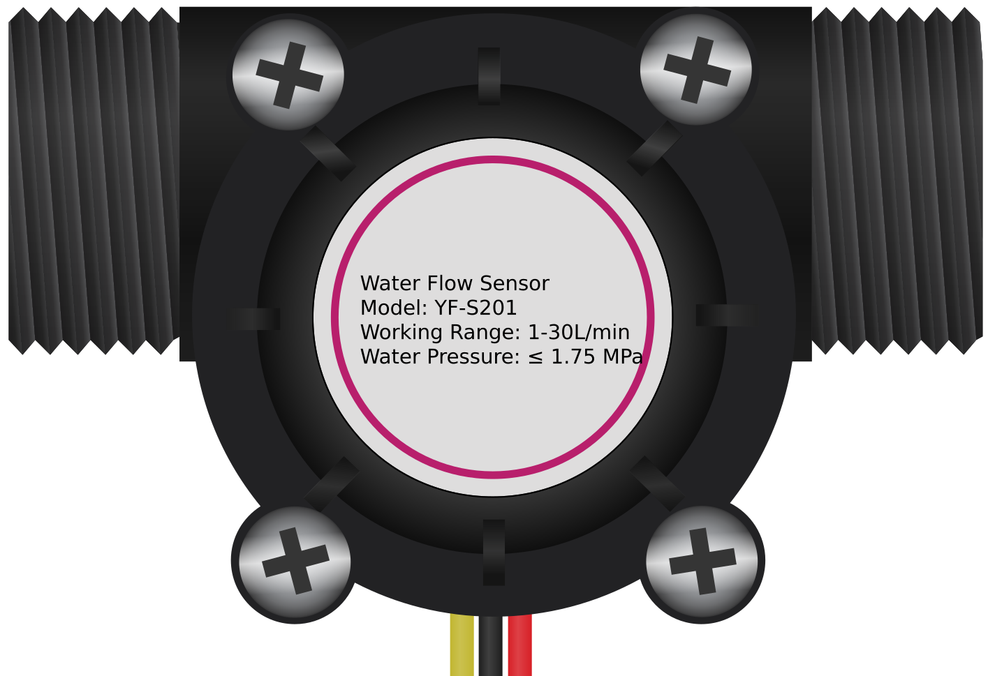
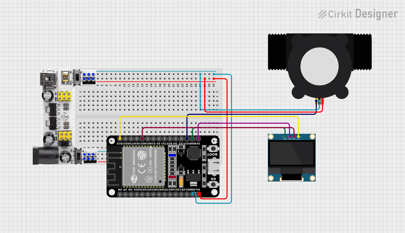
The YF-S201 is a water flow sensor designed to measure the flow rate of water in a pipe. It features a durable plastic body with an internal turbine that rotates as water flows through the sensor. The rotation generates electrical pulses, which can be counted to calculate the flow rate. This sensor is widely used in applications such as irrigation systems, water monitoring, and other scenarios requiring accurate flow measurement.
Explore Projects Built with YF-S201
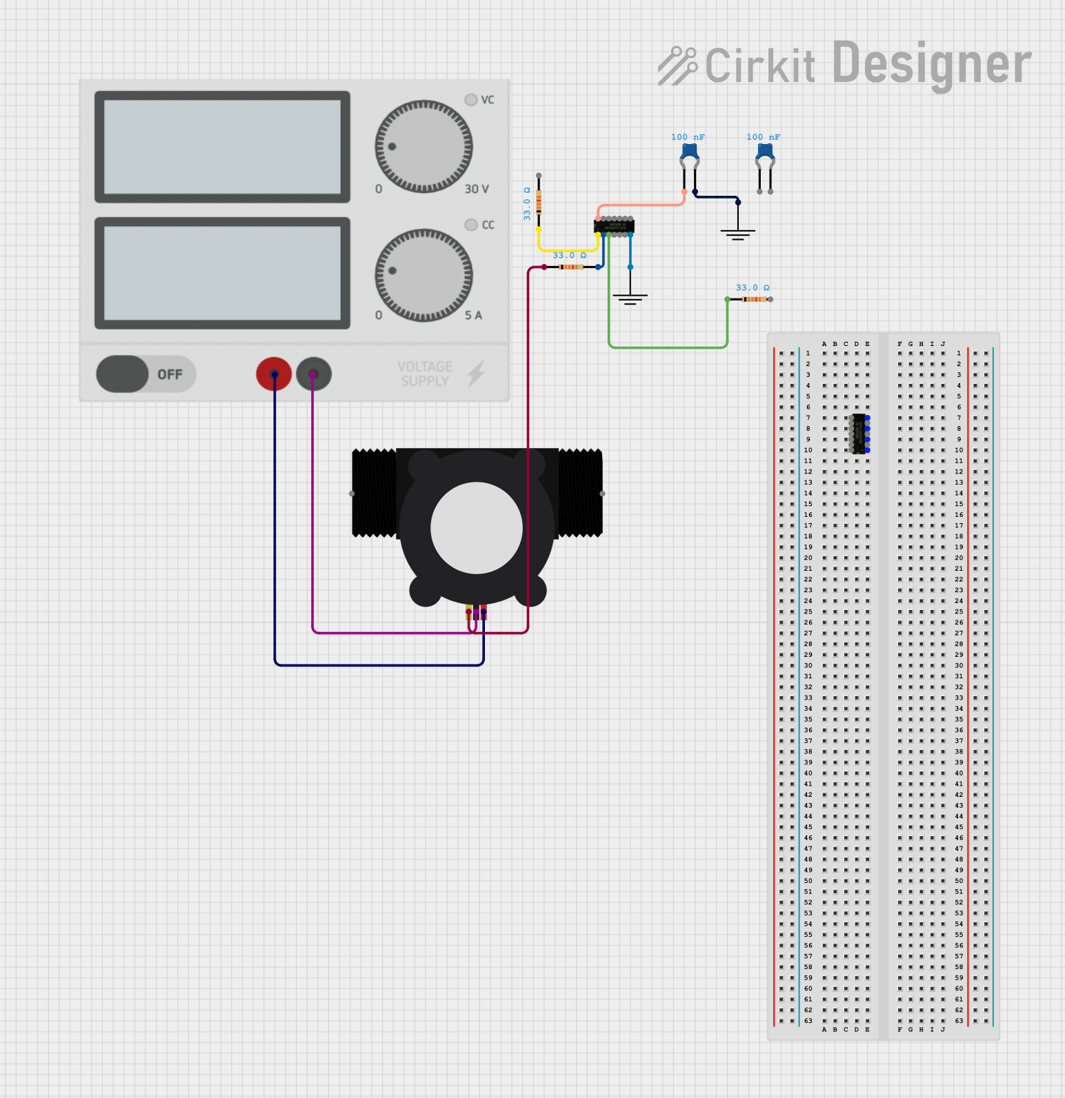
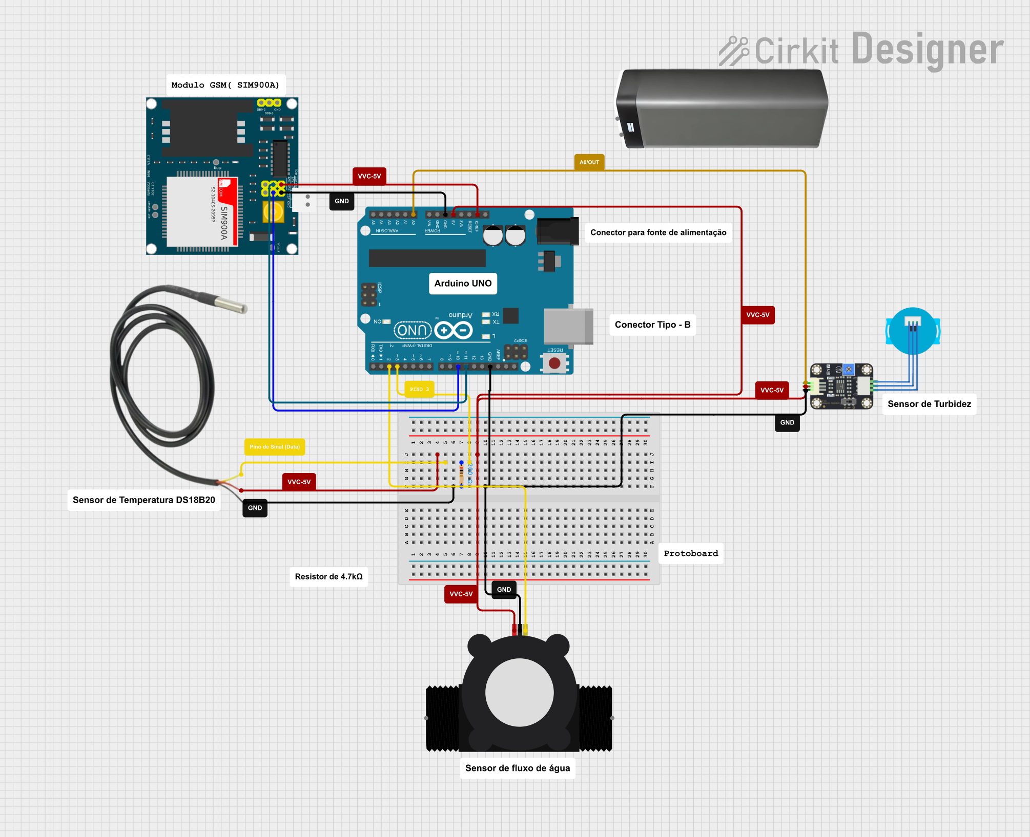
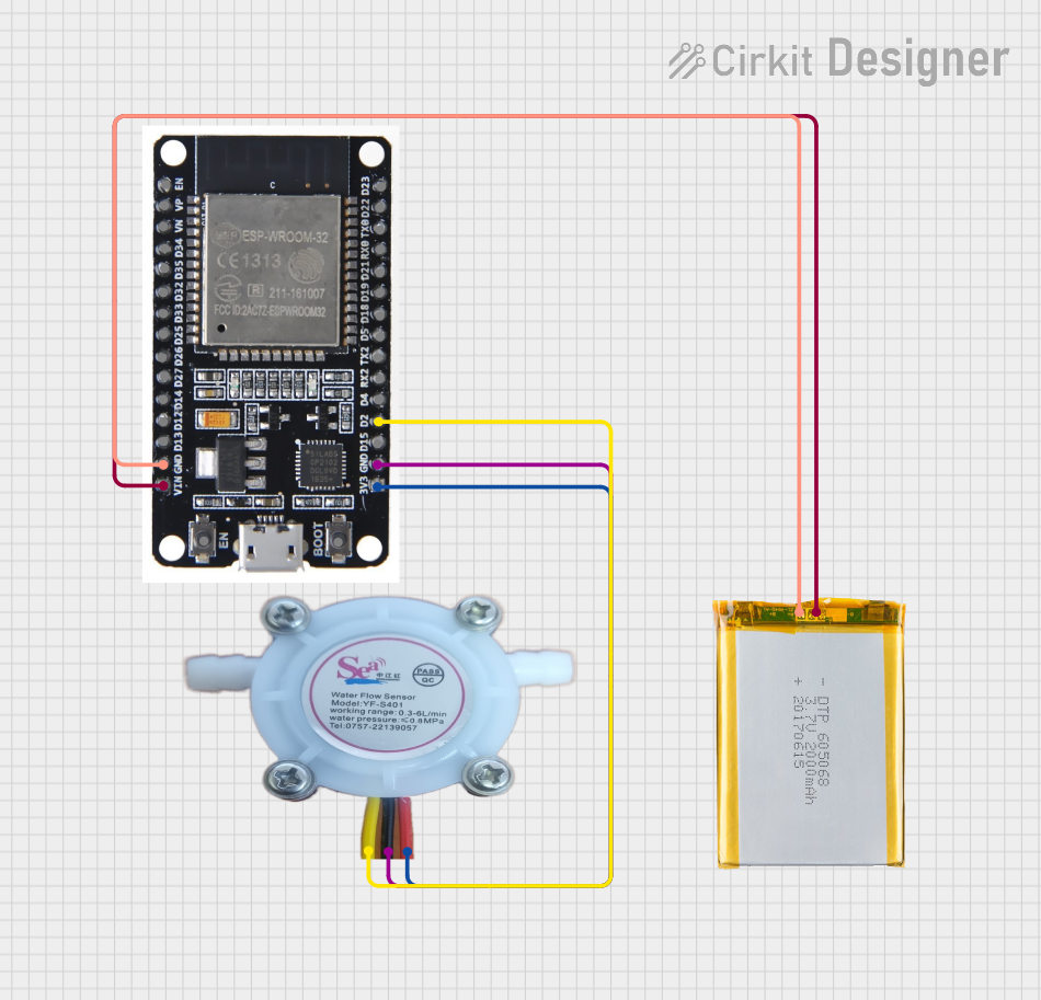
Explore Projects Built with YF-S201
Common Applications
- Irrigation systems for agriculture and gardening
- Water consumption monitoring in residential and industrial setups
- Liquid flow measurement in automated systems
- Leak detection in pipelines
Technical Specifications
The YF-S201 water flow sensor has the following key specifications:
| Parameter | Value |
|---|---|
| Operating Voltage | 5V to 18V DC |
| Operating Current | ≤ 15 mA (at 5V DC) |
| Flow Rate Range | 1 to 30 liters per minute (L/min) |
| Output Pulse Frequency | F = 7.5 * Q (Q = flow rate in L/min) |
| Maximum Water Pressure | 1.75 MPa |
| Operating Temperature | -25°C to 80°C |
| Output Signal | Pulse signal (digital) |
| Sensor Body Material | Plastic (Nylon) |
| Connector Type | 3-pin JST connector |
Pin Configuration
The YF-S201 has a 3-pin JST connector with the following pinout:
| Pin | Name | Description |
|---|---|---|
| 1 | VCC | Power supply (5V to 18V DC) |
| 2 | GND | Ground |
| 3 | Signal | Pulse output signal (connect to microcontroller pin) |
Usage Instructions
How to Use the YF-S201 in a Circuit
- Power the Sensor: Connect the VCC pin to a 5V to 18V DC power source and the GND pin to ground.
- Connect the Signal Pin: Attach the Signal pin to a digital input pin on a microcontroller (e.g., Arduino UNO).
- Read the Pulses: Use the microcontroller to count the pulses generated by the sensor. Each pulse corresponds to a specific volume of water flow.
- Calculate Flow Rate: Use the formula
Flow Rate (L/min) = Pulse Frequency / 7.5to determine the flow rate.
Important Considerations
- Orientation: Install the sensor in the correct orientation as indicated by the arrow on the sensor body, which shows the direction of water flow.
- Debouncing: Use software debouncing to filter out noise in the pulse signal.
- Water Quality: Avoid using the sensor with water containing large particles or debris, as this may damage the turbine.
- Voltage Levels: Ensure the microcontroller's input pin can handle the voltage level of the pulse signal.
Example Code for Arduino UNO
Below is an example of how to use the YF-S201 with an Arduino UNO to measure water flow:
// YF-S201 Water Flow Sensor Example Code
// Connect the Signal pin to Arduino digital pin 2
// Ensure the sensor is powered with 5V and GND is connected

volatile int pulseCount = 0; // Variable to store pulse count
float flowRate = 0.0;        // Variable to store flow rate in L/min
unsigned long lastTime = 0;  // Time of the last calculation

void setup() {
  pinMode(2, INPUT_PULLUP);  // Set pin 2 as input with pull-up resistor
  attachInterrupt(digitalPinToInterrupt(2), countPulse, RISING);
  // Attach interrupt to count pulses on rising edge
  Serial.begin(9600);        // Initialize serial communication
}

void loop() {
  unsigned long currentTime = millis(); // Get current time
  if (currentTime - lastTime >= 1000) { // Calculate flow rate every second
    detachInterrupt(digitalPinToInterrupt(2)); // Temporarily disable interrupt
    flowRate = (pulseCount / 7.5); // Calculate flow rate in L/min
    pulseCount = 0;                // Reset pulse count
    lastTime = currentTime;        // Update last calculation time
    attachInterrupt(digitalPinToInterrupt(2), countPulse, RISING);
    // Re-enable interrupt

    // Print flow rate to serial monitor
    Serial.print("Flow Rate: ");
    Serial.print(flowRate);
    Serial.println(" L/min");
  }
}

// Interrupt service routine to count pulses
void countPulse() {
  pulseCount++; // Increment pulse count on each rising edge
}
Notes on the Code
- The
countPulsefunction is an interrupt service routine (ISR) that increments the pulse count whenever a rising edge is detected on pin 2. - The flow rate is calculated every second and printed to the serial monitor.
- Ensure the Arduino is powered properly and the sensor is connected securely.
Troubleshooting and FAQs
Common Issues
No Output Signal
- Cause: Incorrect wiring or insufficient power supply.
- Solution: Verify the connections and ensure the sensor is powered with 5V to 18V DC.
Inaccurate Flow Rate
- Cause: Incorrect formula or noisy signal.
- Solution: Double-check the formula and implement software debouncing to filter noise.
Sensor Not Responding
- Cause: Blockage in the turbine or damaged sensor.
- Solution: Inspect the sensor for debris or damage and clean it if necessary.
High Pulse Noise
- Cause: Electrical interference or unstable power supply.
- Solution: Use a capacitor across the power supply pins to stabilize the voltage.
FAQs
Q: Can the YF-S201 measure other liquids besides water?
A: The sensor is designed for water and may not provide accurate readings with other liquids. Additionally, certain liquids may damage the sensor's plastic body.
Q: What is the maximum cable length for the sensor?
A: The maximum cable length depends on the environment and signal quality. For best results, keep the cable length under 2 meters.
Q: Can I use the YF-S201 with a 3.3V microcontroller?
A: Yes, but you may need a level shifter to ensure the pulse signal is compatible with the 3.3V logic level.
Q: How do I clean the sensor?
A: Disconnect the sensor, flush it with clean water, and remove any debris from the turbine carefully. Avoid using harsh chemicals.