How to Use PWM Fan Speed Controller: Examples, Pinouts, and Specs
Introduction
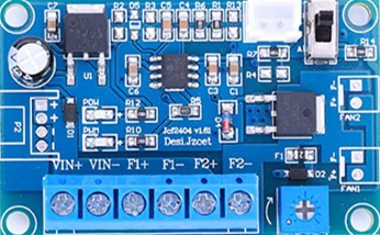
The PWM Fan Speed Controller (Manufacturer: Dpofirs, Part ID: B0CG4TYNP2) is a versatile electronic component designed to regulate the speed of DC fans using Pulse Width Modulation (PWM) technology. By adjusting the width of the pulses in the control signal, this component enables precise control over fan speed, optimizing airflow and reducing noise levels in various applications.
Explore Projects Built with PWM Fan Speed Controller


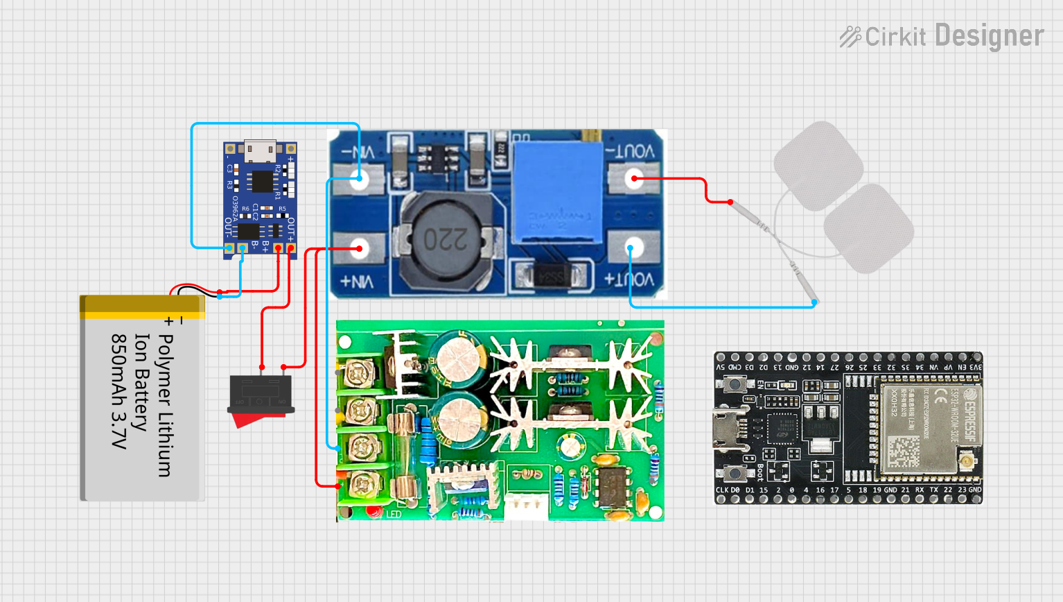
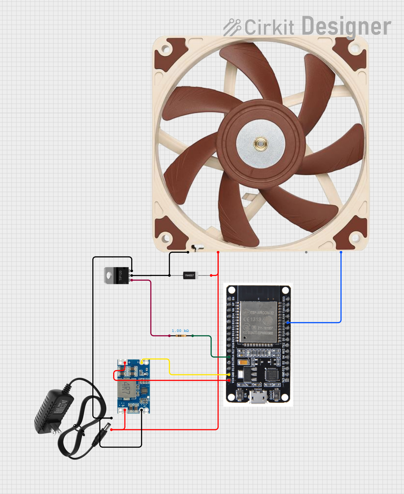
Explore Projects Built with PWM Fan Speed Controller
Common Applications and Use Cases
- Cooling systems in computers, servers, and other electronic devices
- Temperature regulation in industrial equipment
- Ventilation systems in home appliances
- Custom DIY electronics projects requiring fan speed control
Technical Specifications
The following table outlines the key technical details of the PWM Fan Speed Controller:
| Parameter | Value |
|---|---|
| Input Voltage Range | 5V to 12V DC |
| Output Voltage Range | 5V to 12V DC (matches input) |
| Maximum Output Current | 2A |
| PWM Frequency | 25 kHz |
| Duty Cycle Range | 0% to 100% |
| Operating Temperature | -20°C to 60°C |
| Dimensions | 30mm x 20mm x 10mm |
Pin Configuration and Descriptions
The PWM Fan Speed Controller has a simple pin layout for easy integration into circuits. The table below describes each pin:
| Pin Name | Description |
|---|---|
| VIN | Positive DC input voltage (5V to 12V) |
| GND | Ground connection |
| FAN+ | Positive terminal for the fan |
| FAN- | Negative terminal for the fan |
| PWM IN | Optional external PWM signal input (0V to 5V logic) |
Usage Instructions
How to Use the Component in a Circuit
- Power Supply: Connect the VIN pin to a DC power source (5V to 12V) and the GND pin to the ground of the power source.
- Fan Connection: Attach the positive terminal of the fan to the FAN+ pin and the negative terminal to the FAN- pin.
- PWM Control:
- If using the built-in PWM control, adjust the onboard potentiometer to set the desired fan speed.
- For external PWM control, connect a 0V to 5V PWM signal to the PWM IN pin. Ensure the signal frequency is compatible (e.g., 25 kHz).
Important Considerations and Best Practices
- Power Rating: Ensure the fan's voltage and current ratings are within the controller's supported range (5V to 12V, max 2A).
- Heat Dissipation: If operating at high currents, ensure adequate ventilation or heat sinking to prevent overheating.
- PWM Signal: When using an external PWM signal, ensure the duty cycle is within the 0% to 100% range for proper operation.
- Polarity: Double-check the polarity of all connections to avoid damage to the component or the fan.
Example: Using with an Arduino UNO
The PWM Fan Speed Controller can be easily interfaced with an Arduino UNO for automated fan speed control. Below is an example code snippet:
// Example: Controlling a PWM Fan Speed Controller with Arduino UNO
// Connect the PWM IN pin of the controller to Arduino pin 9

const int pwmPin = 9; // PWM output pin connected to PWM IN of the controller

void setup() {
  pinMode(pwmPin, OUTPUT); // Set pin 9 as an output
}

void loop() {
  // Gradually increase fan speed
  for (int dutyCycle = 0; dutyCycle <= 255; dutyCycle++) {
    analogWrite(pwmPin, dutyCycle); // Write PWM signal to the controller
    delay(10); // Wait 10ms for smooth transition
  }

  // Gradually decrease fan speed
  for (int dutyCycle = 255; dutyCycle >= 0; dutyCycle--) {
    analogWrite(pwmPin, dutyCycle); // Write PWM signal to the controller
    delay(10); // Wait 10ms for smooth transition
  }
}
Troubleshooting and FAQs
Common Issues and Solutions
Fan Does Not Spin
- Cause: Incorrect wiring or insufficient input voltage.
- Solution: Verify all connections and ensure the input voltage matches the fan's requirements.
Fan Speed Does Not Change
- Cause: PWM signal not properly applied or potentiometer not adjusted.
- Solution: Check the PWM IN pin for a valid signal or adjust the onboard potentiometer.
Overheating
- Cause: Excessive current draw or poor ventilation.
- Solution: Use a fan with a lower current rating or improve heat dissipation.
Noise or Vibration
- Cause: Fan operating at very low speeds.
- Solution: Increase the minimum duty cycle to avoid unstable operation.
FAQs
Q: Can I use this controller with a 24V fan?
A: No, the controller supports a maximum input voltage of 12V. Using a 24V fan may damage the component.
Q: What happens if I connect both the potentiometer and an external PWM signal?
A: The external PWM signal will override the onboard potentiometer. Ensure the external signal is within the specified range.
Q: Can I control multiple fans with this controller?
A: Yes, but ensure the total current draw of all fans does not exceed 2A.
Q: Is this controller compatible with 3-pin or 4-pin fans?
A: This controller is designed for 2-pin DC fans. For 3-pin or 4-pin fans, additional modifications may be required.