Cirkit Designer Logo
Cirkit Designer
Your all-in-one circuit design IDE
Home / 
Component Documentation

How to Use Adafruit 1.3 Color TFT Bonnet for Raspberry Pi - 240x240 TFT + Joystick Add-on: Examples, Pinouts, and Specs

Image of Adafruit 1.3 Color TFT Bonnet for Raspberry Pi - 240x240 TFT + Joystick Add-on
Cirkit Designer LogoDesign with Adafruit 1.3 Color TFT Bonnet for Raspberry Pi - 240x240 TFT + Joystick Add-on in Cirkit Designer

Introduction

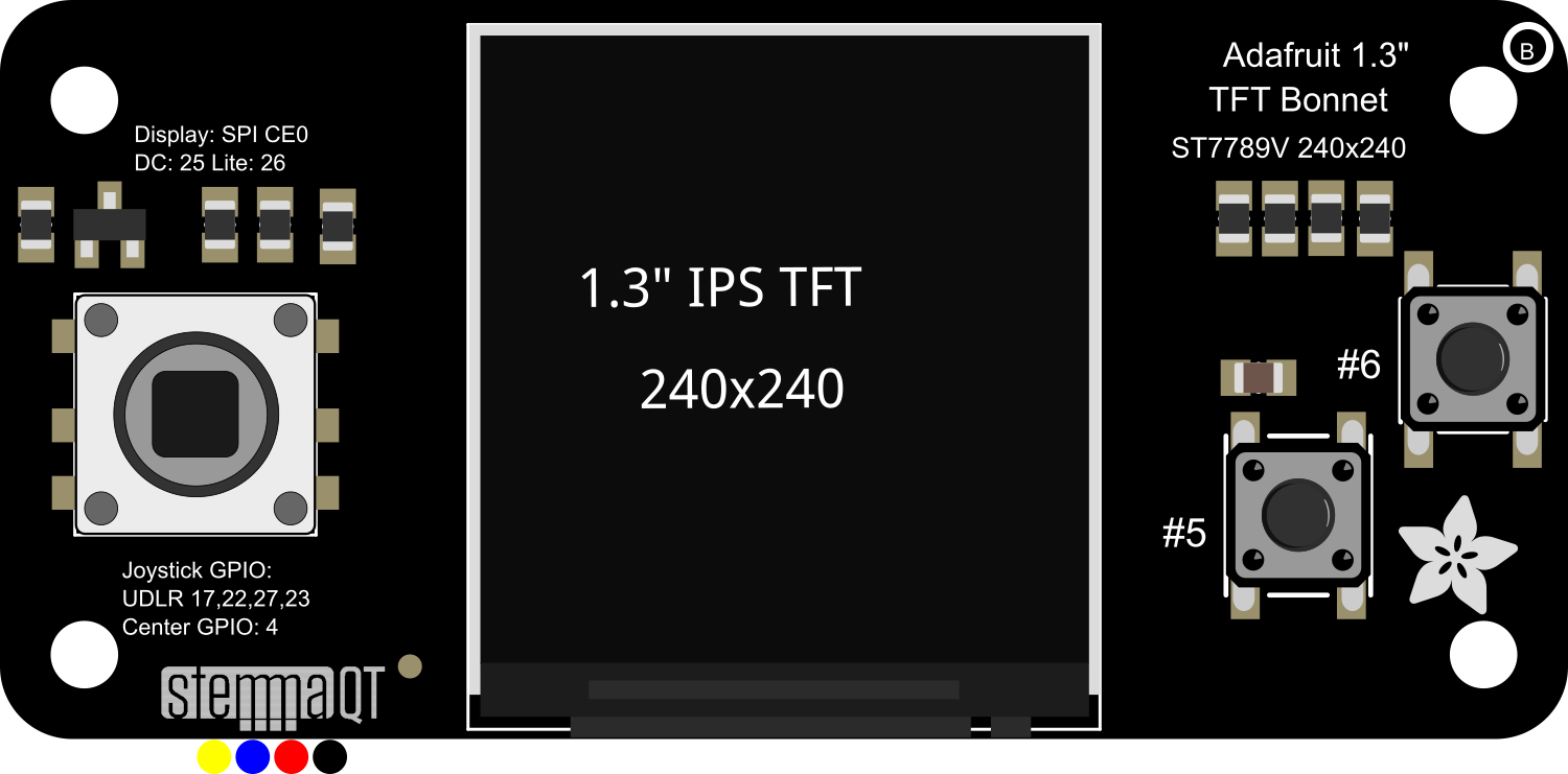
The Adafruit 1.3" Color TFT Bonnet is an add-on board designed for the Raspberry Pi, featuring a vibrant 1.3-inch TFT display with a resolution of 240x240 pixels. This compact and versatile bonnet not only provides a colorful output interface for your projects but also includes a 5-way joystick and three tactile buttons for user input, making it an ideal choice for portable gaming, user interfaces, or any project requiring a compact display and simple controls.

Explore Projects Built with Adafruit 1.3 Color TFT Bonnet for Raspberry Pi - 240x240 TFT + Joystick Add-on

Use Cirkit Designer to design, explore, and prototype these projects online. Some projects support real-time simulation. Click "Open Project" to start designing instantly!
Raspberry Pi Pico W Controlled RGB LED with Joystick Interaction
Image of Snap Project #2: A project utilizing Adafruit 1.3 Color TFT Bonnet for Raspberry Pi - 240x240 TFT + Joystick Add-on in a practical application
This circuit features a Raspberry Pi Pico W microcontroller connected to a KY-023 Dual Axis Joystick Module and an RGB LED with individual resistors on each color channel. The joystick's analog outputs (VRx and VRy) are read by the microcontroller to control the color and brightness of the RGB LED in a dynamic fashion, as defined by the embedded Python code. The code implements a color-changing sequence that responds to the joystick's position, creating an interactive lighting system.
Cirkit Designer LogoOpen Project in Cirkit Designer
Raspberry Pi Pico W Controlled RGB LED with Joystick Interaction
Image of Snap Project #5: A project utilizing Adafruit 1.3 Color TFT Bonnet for Raspberry Pi - 240x240 TFT + Joystick Add-on in a practical application
This circuit features a Raspberry Pi Pico W microcontroller interfaced with a KY-023 Dual Axis Joystick Module and a four-pin RGB LED. The joystick's position controls the color of the RGB LED through PWM signals, with resistors limiting current to the LED's cathodes and a capacitor potentially used for debouncing the joystick's switch. The embedded code cycles through color sequences based on the joystick's Y-axis position, creating a dynamic lighting effect.
Cirkit Designer LogoOpen Project in Cirkit Designer
NodeMCU ESP8266 Controlled Drone with TFT Display and nRF24L01 Communication
Image of receiver/transmitter: A project utilizing Adafruit 1.3 Color TFT Bonnet for Raspberry Pi - 240x240 TFT + Joystick Add-on in a practical application
This circuit features a NodeMCU V3 ESP8266 microcontroller interfaced with an LCD TFT screen, an nRF24L01 wireless transceiver, and an Adafruit Analog 2-Axis Joystick. The NodeMCU collects joystick inputs and displays information on the TFT screen, while also communicating with other devices via the nRF24L01 module. The circuit is powered by a 9V battery, with the NodeMCU regulating the voltage for other components.
Cirkit Designer LogoOpen Project in Cirkit Designer
Raspberry Pi 5 Smart Sensor Hub with OLED Display and Camera
Image of dash cam: A project utilizing Adafruit 1.3 Color TFT Bonnet for Raspberry Pi - 240x240 TFT + Joystick Add-on in a practical application
This circuit integrates a Raspberry Pi 5 with various peripherals including an OV7670 camera, a BMI160 accelerometer/gyro sensor, and a 2.42 inch OLED display. It also includes a red LED and a breadboard power supply module, enabling the Raspberry Pi to interface with the sensors and display for data acquisition and visualization.
Cirkit Designer LogoOpen Project in Cirkit Designer

Explore Projects Built with Adafruit 1.3 Color TFT Bonnet for Raspberry Pi - 240x240 TFT + Joystick Add-on

Use Cirkit Designer to design, explore, and prototype these projects online. Some projects support real-time simulation. Click "Open Project" to start designing instantly!
Image of Snap Project #2: A project utilizing Adafruit 1.3 Color TFT Bonnet for Raspberry Pi - 240x240 TFT + Joystick Add-on in a practical application
Raspberry Pi Pico W Controlled RGB LED with Joystick Interaction
This circuit features a Raspberry Pi Pico W microcontroller connected to a KY-023 Dual Axis Joystick Module and an RGB LED with individual resistors on each color channel. The joystick's analog outputs (VRx and VRy) are read by the microcontroller to control the color and brightness of the RGB LED in a dynamic fashion, as defined by the embedded Python code. The code implements a color-changing sequence that responds to the joystick's position, creating an interactive lighting system.
Cirkit Designer LogoOpen Project in Cirkit Designer
Image of Snap Project #5: A project utilizing Adafruit 1.3 Color TFT Bonnet for Raspberry Pi - 240x240 TFT + Joystick Add-on in a practical application
Raspberry Pi Pico W Controlled RGB LED with Joystick Interaction
This circuit features a Raspberry Pi Pico W microcontroller interfaced with a KY-023 Dual Axis Joystick Module and a four-pin RGB LED. The joystick's position controls the color of the RGB LED through PWM signals, with resistors limiting current to the LED's cathodes and a capacitor potentially used for debouncing the joystick's switch. The embedded code cycles through color sequences based on the joystick's Y-axis position, creating a dynamic lighting effect.
Cirkit Designer LogoOpen Project in Cirkit Designer
Image of receiver/transmitter: A project utilizing Adafruit 1.3 Color TFT Bonnet for Raspberry Pi - 240x240 TFT + Joystick Add-on in a practical application
NodeMCU ESP8266 Controlled Drone with TFT Display and nRF24L01 Communication
This circuit features a NodeMCU V3 ESP8266 microcontroller interfaced with an LCD TFT screen, an nRF24L01 wireless transceiver, and an Adafruit Analog 2-Axis Joystick. The NodeMCU collects joystick inputs and displays information on the TFT screen, while also communicating with other devices via the nRF24L01 module. The circuit is powered by a 9V battery, with the NodeMCU regulating the voltage for other components.
Cirkit Designer LogoOpen Project in Cirkit Designer
Image of dash cam: A project utilizing Adafruit 1.3 Color TFT Bonnet for Raspberry Pi - 240x240 TFT + Joystick Add-on in a practical application
Raspberry Pi 5 Smart Sensor Hub with OLED Display and Camera
This circuit integrates a Raspberry Pi 5 with various peripherals including an OV7670 camera, a BMI160 accelerometer/gyro sensor, and a 2.42 inch OLED display. It also includes a red LED and a breadboard power supply module, enabling the Raspberry Pi to interface with the sensors and display for data acquisition and visualization.
Cirkit Designer LogoOpen Project in Cirkit Designer

Common Applications and Use Cases

  • Portable gaming systems
  • Interactive displays for projects
  • User interfaces for IoT devices
  • DIY electronics projects requiring visual output and simple navigation

Technical Specifications

Display

  • Size: 1.3 inches diagonal
  • Resolution: 240x240 pixels
  • Interface: SPI

Joystick

  • Type: 5-way digital joystick
  • Connections: Directly wired to GPIO pins

Buttons

  • Quantity: 3 tactile buttons
  • Connections: Directly wired to GPIO pins

Power

  • Supply Voltage: 3.3V to 5V DC
  • Current Draw: Typically 100mA (depends on brightness and content displayed)

Pin Configuration and Descriptions

Pin Number Description Notes
1 3V3 Power supply (3.3V)
2 5V Power supply (5V)
3 GPIO2 SDA for I2C communication
4 5V Power supply (5V)
5 GPIO3 SCL for I2C communication
6 Ground Ground connection
... ... ...
26 GPIO7 SPI CE1 for display
... ... ...
36 GPIO16 Button A
37 GPIO26 Button B
38 GPIO20 Button C
... ... ...
40 GPIO21 Joystick button

Note: This table is not exhaustive. Refer to the full pinout diagram for complete details.

Usage Instructions

Connecting to Raspberry Pi

  1. Power off your Raspberry Pi.
  2. Align the 40-pin GPIO connector of the TFT Bonnet with the GPIO header on the Raspberry Pi.
  3. Gently press down to connect the bonnet to the Raspberry Pi.

Software Setup

Before using the display, you need to install the necessary software. Adafruit provides a Python library that makes it easy to draw to the display and read inputs from the joystick and buttons.

  1. Update your Raspberry Pi with the latest packages:
sudo apt-get update
sudo apt-get upgrade
  1. Install the Adafruit Python library for the TFT display and joystick:
sudo pip3 install adafruit-circuitpython-rgb-display
sudo pip3 install adafruit-circuitpython-joystick
  1. Enable SPI and I2C interfaces on your Raspberry Pi using raspi-config:
sudo raspi-config

Navigate to Interfacing Options > SPI and I2C and enable both.

Running a Test Script

After installing the necessary libraries and enabling the interfaces, you can run a test script to ensure the display and joystick are working correctly.

import board
import digitalio
import adafruit_rgb_display.st7789 as st7789

Configuration for CS and DC pins:

cs_pin = digitalio.DigitalInOut(board.CE0) dc_pin = digitalio.DigitalInOut(board.D25) reset_pin = None

Configuring the display:

display = st7789.ST7789( board.SPI(), cs=cs_pin, dc=dc_pin, rst=reset_pin, width=240, height=240, baudrate=64000000, rotation=180 )

Clear the display to a solid color:

display.fill(0x7521)

More code to interact with the joystick and buttons goes here...


*Note: This is a basic example to get the display up and running. For full functionality, including joystick and button input, refer to the Adafruit documentation and example code.*

Important Considerations and Best Practices

  • Always power off the Raspberry Pi before attaching or detaching the TFT Bonnet to prevent damage.
  • Use a proper power supply that can handle the current requirements of the Raspberry Pi and the TFT Bonnet.
  • Avoid exposing the display to direct sunlight for extended periods to prevent damage.

Troubleshooting and FAQs

Common Issues

  • Display not lighting up: Ensure that the bonnet is properly seated on the GPIO pins and that SPI is enabled.
  • Inputs not responding: Verify that the I2C interface is enabled and that the GPIO pins are not being used by other processes.

Solutions and Tips for Troubleshooting

  • Double-check the wiring and connections if you're using the bonnet with a breadboard or custom setup.
  • Review the software installation steps to ensure all necessary libraries are installed.
  • Consult the Raspberry Pi's dmesg and lsmod commands to check for any kernel messages or modules related to SPI and I2C.

FAQs

Q: Can I use this bonnet with other models of Raspberry Pi? A: Yes, the bonnet is compatible with any Raspberry Pi model that has a 40-pin GPIO header.

Q: How do I update the display content? A: You can use the Adafruit Python library to draw text, shapes, and images to the display. Check the library documentation for detailed functions and examples.

Q: Can I use this bonnet with other programming languages? A: While Adafruit provides a Python library, you can use any language that can interface with the SPI and I2C protocols, provided you have the necessary libraries or write your own interface code.

For further assistance, visit the Adafruit forums or the Raspberry Pi community forums.