
How to Use Fan: Examples, Pinouts, and Specs
 Design with Fan in Cirkit Designer
Introduction
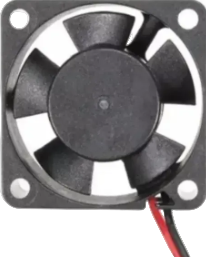
A fan is an electromechanical device designed to create airflow, which is essential for cooling or ventilating an area. In electronic systems, fans are commonly used to dissipate heat generated by components such as processors, power supplies, and other heat-sensitive devices. Proper cooling ensures the longevity and reliability of electronic equipment.
The Arduino Nano can be used to control a fan for various applications, such as temperature-based cooling systems, automated ventilation, or custom projects requiring airflow management.
Explore Projects Built with Fan
 Open Project in Cirkit Designer
 Open Project in Cirkit Designer
 Open Project in Cirkit Designer
 Open Project in Cirkit Designer
Explore Projects Built with Fan
Open Project in Cirkit DesignerOpen Project in Cirkit DesignerOpen Project in Cirkit DesignerOpen Project in Cirkit DesignerCommon Applications
- Cooling electronic components (e.g., CPUs, power supplies)
- Ventilation in enclosures or cabinets
- Temperature-controlled systems
- Air circulation in robotics or IoT devices
Technical Specifications
Below are the general specifications for a typical DC fan compatible with Arduino Nano:
| Parameter | Value |
|---|---|
| Operating Voltage | 5V or 12V (depending on the fan) |
| Current Consumption | 100mA to 300mA |
| Power Rating | 0.5W to 3.6W |
| Speed | 2000 to 5000 RPM |
| Airflow | 10 to 50 CFM (Cubic Feet/Minute) |
| Connector Type | 2-pin or 3-pin |
Pin Configuration
For a 3-pin fan, the pinout is as follows:
| Pin | Name | Description |
|---|---|---|
| 1 | GND | Ground connection |
| 2 | VCC | Power supply (5V or 12V, depending on the fan) |
| 3 | Tachometer | Optional signal pin for speed monitoring (RPM output) |
For a 2-pin fan, the pinout is simpler:
| Pin | Name | Description |
|---|---|---|
| 1 | GND | Ground connection |
| 2 | VCC | Power supply (5V or 12V, depending on the fan) |
Usage Instructions
Connecting the Fan to an Arduino Nano
To control a fan using an Arduino Nano, you can use a transistor or MOSFET as a switch, since the Nano cannot directly supply the current required by the fan. Below is a step-by-step guide:
Components Required:
- Arduino Nano
- DC fan (5V or 12V)
- NPN transistor (e.g., 2N2222) or MOSFET (e.g., IRF540N)
- Diode (e.g., 1N4007) to protect against back EMF
- Resistor (e.g., 1kΩ for the transistor base)
- External power supply (if using a 12V fan)
Circuit Diagram:
- Connect the fan's VCC pin to the external power supply (5V or 12V).
- Connect the fan's GND pin to the collector of the NPN transistor (or the drain of the MOSFET).
- Connect the emitter of the transistor (or the source of the MOSFET) to GND.
- Place a diode across the fan terminals (cathode to VCC, anode to GND) to protect against voltage spikes.
- Connect a 1kΩ resistor between the Arduino Nano's digital pin (e.g., D9) and the base of the transistor (or the gate of the MOSFET).
- Connect the external power supply's GND to the Arduino Nano's GND.
Arduino Code: Below is an example code to control the fan using PWM (Pulse Width Modulation) for speed control:
// Define the pin connected to the transistor or MOSFET
const int fanPin = 9; // PWM pin on Arduino Nano

void setup() {
  pinMode(fanPin, OUTPUT); // Set the fan pin as an output
}

void loop() {
  // Example: Gradually increase and decrease fan speed
  for (int speed = 0; speed <= 255; speed++) {
    analogWrite(fanPin, speed); // Set fan speed (0-255)
    delay(10); // Small delay for smooth speed transition
  }
  for (int speed = 255; speed >= 0; speed--) {
    analogWrite(fanPin, speed); // Decrease fan speed
    delay(10); // Small delay for smooth speed transition
  }
}
Important Considerations
- Voltage Compatibility: Ensure the fan's operating voltage matches the power supply.
- Current Requirements: Verify that the transistor or MOSFET can handle the fan's current.
- Back EMF Protection: Always use a diode to protect the circuit from voltage spikes caused by the fan's motor.
- PWM Frequency: Some fans may produce noise at certain PWM frequencies. Experiment with different frequencies if needed.
Troubleshooting and FAQs
Common Issues
Fan Not Spinning:
- Check the power supply voltage and connections.
- Verify that the transistor or MOSFET is functioning correctly.
- Ensure the Arduino Nano is outputting the correct PWM signal.
Fan Spins at Full Speed Only:
- Confirm that the PWM pin is correctly connected to the transistor or MOSFET.
- Check the Arduino code for proper PWM signal generation.
Fan Produces Noise:
- Try adjusting the PWM frequency in the Arduino code.
- Ensure the fan is securely mounted to reduce vibrations.
Arduino Resets When Fan Starts:
- This may occur if the fan draws too much current. Use an external power supply for the fan.
FAQs
Q: Can I connect the fan directly to the Arduino Nano?
A: No, the Arduino Nano cannot supply enough current to drive a fan directly. Use a transistor or MOSFET as a switch.
Q: How do I monitor the fan's speed?
A: If your fan has a tachometer pin, connect it to a digital input pin on the Arduino Nano and use an interrupt to measure the RPM.
Q: Can I use a 12V fan with the Arduino Nano?
A: Yes, but you must use an external 12V power supply and ensure proper connections with a transistor or MOSFET.
Q: What is the purpose of the diode across the fan terminals?
A: The diode protects the circuit from voltage spikes caused by the fan's motor when it turns off.