How to Use XL6009: Examples, Pinouts, and Specs
Introduction
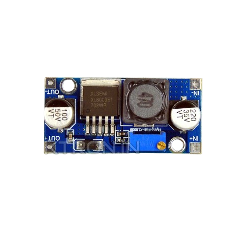
The XL6009 is a high-performance, step-up (boost) DC-DC converter designed to efficiently increase a lower input voltage to a higher output voltage. It is based on a high-frequency switching regulator and features a wide input voltage range, high efficiency, and compact size. The XL6009 is commonly used in applications requiring a stable output voltage from a varying input voltage, such as battery-powered devices, solar power systems, LED drivers, and portable electronics.
Explore Projects Built with XL6009


Explore Projects Built with XL6009
Common Applications:
- Battery-powered devices (e.g., powering 12V devices from a 5V USB power bank)
- Solar power systems
- LED drivers
- Portable electronics
- Industrial control systems
- DIY electronics projects
Technical Specifications
The XL6009 is a versatile component with the following key technical specifications:
| Parameter | Value |
|---|---|
| Input Voltage Range | 3V to 32V |
| Output Voltage Range | 5V to 35V |
| Maximum Output Current | 4A (with proper heat dissipation) |
| Switching Frequency | 400 kHz |
| Efficiency | Up to 94% |
| Output Ripple | <50 mV (depending on load and filtering) |
| Operating Temperature | -40°C to +85°C |
Pin Configuration and Descriptions
The XL6009 is typically available as part of a module with the following pin configuration:
| Pin Name | Description |
|---|---|
| VIN | Input voltage pin. Connect the positive terminal of the input power source here. |
| GND | Ground pin. Connect to the negative terminal of the input power source. |
| VOUT | Output voltage pin. Provides the boosted output voltage. |
| EN | Enable pin. Used to enable or disable the module (active high). |
Usage Instructions
How to Use the XL6009 in a Circuit
Connect the Input Voltage (VIN):
- Connect the positive terminal of your input power source (e.g., battery or power supply) to the
VINpin. - Connect the negative terminal of the input power source to the
GNDpin.
- Connect the positive terminal of your input power source (e.g., battery or power supply) to the
Connect the Output Voltage (VOUT):
- Connect the load (e.g., LED, motor, or other device) to the
VOUTpin. - Ensure the load's ground is connected to the
GNDpin.
- Connect the load (e.g., LED, motor, or other device) to the
Adjust the Output Voltage:
- Use the onboard potentiometer (if available) to adjust the output voltage.
- Turn the potentiometer clockwise to increase the output voltage and counterclockwise to decrease it.
- Use a multimeter to measure the output voltage while adjusting.
Enable the Module:
- If the
ENpin is available, ensure it is connected to a high logic level (e.g., 3.3V or 5V) to enable the module. - If unused, the
ENpin can be left floating or tied toVIN.
- If the
Important Considerations and Best Practices
- Input Voltage Range: Ensure the input voltage is within the specified range (3V to 32V). Exceeding this range may damage the module.
- Output Voltage Range: Adjust the output voltage within the specified range (5V to 35V). Avoid exceeding the maximum voltage rating of your load.
- Heat Dissipation: For high current applications, ensure proper heat dissipation by adding a heatsink or active cooling to the module.
- Filtering Capacitors: Add external capacitors (e.g., electrolytic or ceramic) at the input and output to reduce voltage ripple and improve stability.
- Load Current: Do not exceed the maximum output current of 4A. For high current loads, ensure the module is adequately cooled.
Example: Using XL6009 with Arduino UNO
The XL6009 can be used to power an Arduino UNO from a lower voltage source, such as a 3.7V Li-ion battery. Below is an example circuit and code:
Circuit Connections:
- Connect the battery's positive terminal to the
VINpin of the XL6009. - Connect the battery's negative terminal to the
GNDpin of the XL6009. - Adjust the XL6009's output voltage to 9V using the potentiometer.
- Connect the
VOUTpin of the XL6009 to the Arduino UNO'sVINpin. - Connect the
GNDpin of the XL6009 to the Arduino UNO'sGNDpin.
Example Code:
// Example code to blink an LED on Arduino UNO powered by XL6009
// Ensure the XL6009 output is set to 9V before connecting to Arduino

const int ledPin = 13; // Built-in LED pin on Arduino UNO

void setup() {
  pinMode(ledPin, OUTPUT); // Set LED pin as output
}

void loop() {
  digitalWrite(ledPin, HIGH); // Turn the LED on
  delay(1000);                // Wait for 1 second
  digitalWrite(ledPin, LOW);  // Turn the LED off
  delay(1000);                // Wait for 1 second
}
Troubleshooting and FAQs
Common Issues and Solutions
No Output Voltage:
- Cause: Input voltage is too low or not connected properly.
- Solution: Verify the input voltage is within the specified range and connections are secure.
Output Voltage is Unstable:
- Cause: Insufficient filtering or high load current.
- Solution: Add external capacitors (e.g., 100µF electrolytic) at the input and output.
Module Overheats:
- Cause: Excessive load current or poor heat dissipation.
- Solution: Reduce the load current or add a heatsink to the module.
Cannot Adjust Output Voltage:
- Cause: Potentiometer is damaged or incorrectly adjusted.
- Solution: Replace the potentiometer or ensure it is turned slowly while monitoring the output voltage.
FAQs
Q1: Can the XL6009 step down voltage?
A1: No, the XL6009 is a step-up (boost) converter and cannot step down voltage. Use a buck converter for step-down applications.
Q2: What is the maximum input voltage for the XL6009?
A2: The maximum input voltage is 32V. Exceeding this value may damage the module.
Q3: Can I use the XL6009 to power a Raspberry Pi?
A3: Yes, but ensure the output voltage is set to 5V and the module can handle the current requirements of the Raspberry Pi.
Q4: How do I reduce output ripple?
A4: Add external capacitors (e.g., 100µF or higher) at the output and ensure proper grounding.
By following this documentation, you can effectively use the XL6009 in your projects and troubleshoot common issues.