How to Use EM-18 RFID READER MODULE: Examples, Pinouts, and Specs
Introduction
The EM-18 RFID Reader Module is a compact and efficient device designed for reading RFID tags. Operating at a frequency of 125 kHz, it can detect and read RFID tags from a distance of up to 10 cm. The module outputs the tag data in a serial format, making it highly compatible with microcontrollers, such as Arduino, and other digital systems.
Explore Projects Built with EM-18 RFID READER MODULE

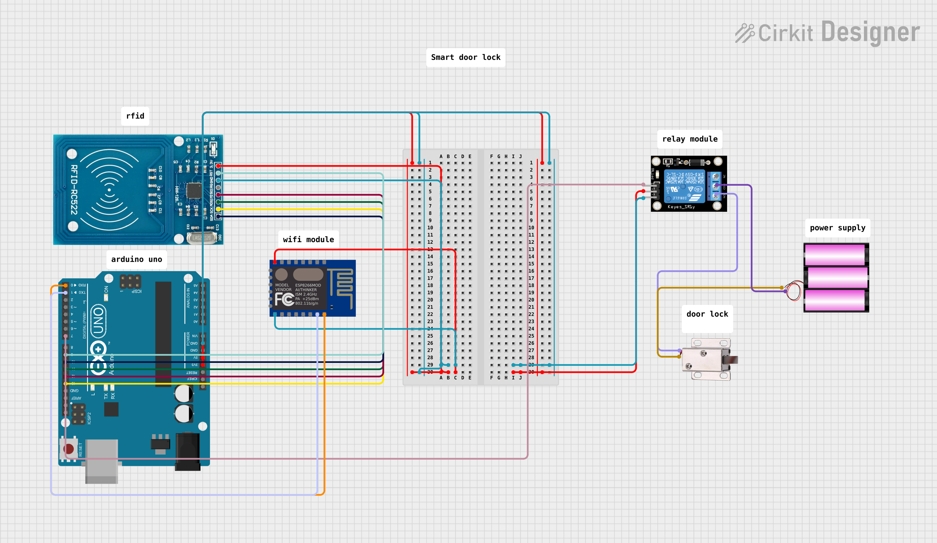
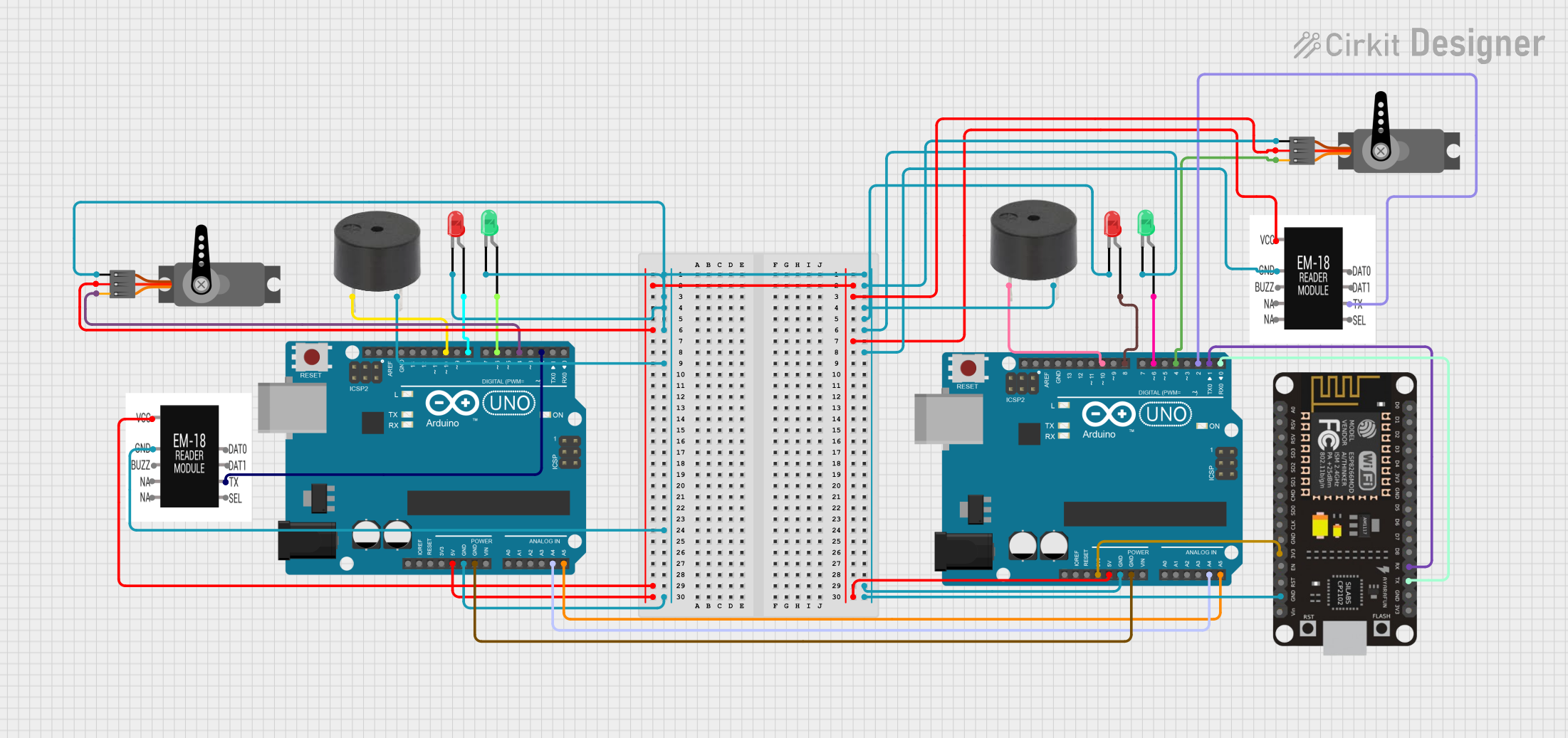
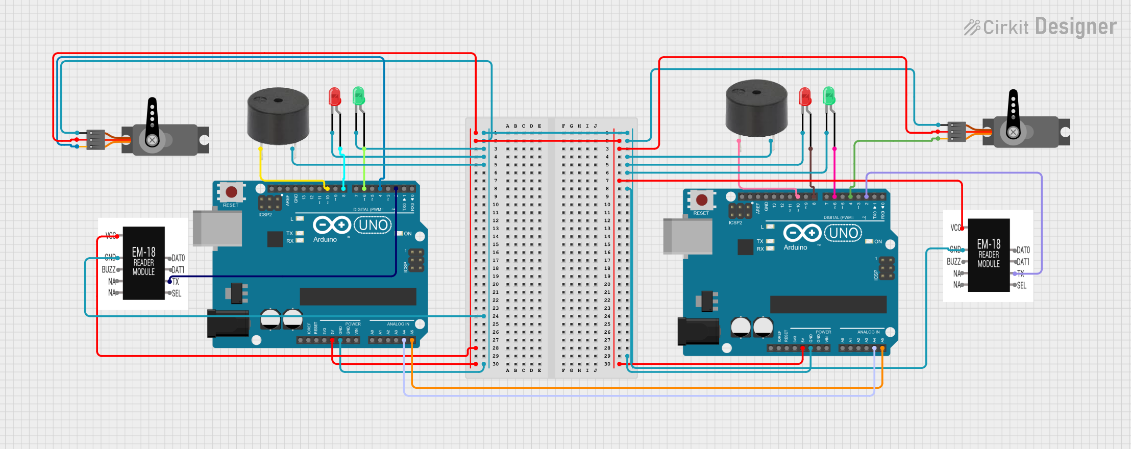
Explore Projects Built with EM-18 RFID READER MODULE
Common Applications
- Access control systems (e.g., door locks, attendance systems)
- Inventory management and tracking
- Payment systems
- Security and authentication systems
- Embedded systems requiring RFID functionality
Technical Specifications
Below are the key technical details and pin configuration for the EM-18 RFID Reader Module:
Key Technical Details
| Parameter | Value |
|---|---|
| Operating Frequency | 125 kHz |
| Operating Voltage | 4.5V to 5.5V DC |
| Current Consumption | 50 mA (typical) |
| Communication Interface | UART (TTL) and Wiegand |
| Baud Rate (UART) | 9600 bps |
| Reading Distance | Up to 10 cm |
| Supported RFID Tags | 125 kHz passive tags |
| Dimensions | 32 mm x 32 mm x 8 mm |
| Operating Temperature | -10°C to +70°C |
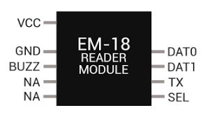
Pin Configuration and Descriptions
The EM-18 module has a total of 7 pins. The table below describes each pin:
| Pin Number | Pin Name | Description |
|---|---|---|
| 1 | VCC | Power supply input (4.5V to 5.5V DC). |
| 2 | GND | Ground connection. |
| 3 | TX | UART serial data output (transmits RFID tag data). |
| 4 | RX | UART serial data input (not commonly used; for advanced configurations). |
| 5 | BEEP | Buzzer control pin (active high). |
| 6 | LED | LED control pin (active high). |
| 7 | ANT | Antenna pin (internally connected; not used externally). |
Usage Instructions
How to Use the EM-18 RFID Reader Module in a Circuit
- Power the Module: Connect the VCC pin to a 5V DC power source and the GND pin to ground.
- Connect to a Microcontroller:
- Connect the TX pin of the EM-18 to the RX pin of the microcontroller (e.g., Arduino UNO).
- Ensure the microcontroller's UART baud rate is set to 9600 bps to match the module's output.
- Read RFID Tags:
- When an RFID tag is brought within the module's range (up to 10 cm), the module reads the tag's unique ID.
- The ID is transmitted via the TX pin in a serial format.
- Optional Connections:
- Use the BEEP pin to control an external buzzer for audible feedback.
- Use the LED pin to control an external LED for visual feedback.
Important Considerations and Best Practices
- Power Supply: Ensure a stable 5V DC power supply to avoid erratic behavior.
- Tag Compatibility: Use only 125 kHz passive RFID tags for proper operation.
- Interference: Avoid placing the module near metal objects or other electronic devices that may cause interference.
- Antenna Range: Ensure the RFID tag is within the specified range (up to 10 cm) for reliable reading.
Example: Connecting EM-18 to Arduino UNO
Below is an example of how to connect and use the EM-18 RFID Reader Module with an Arduino UNO:
Circuit Connections
| EM-18 Pin | Arduino UNO Pin |
|---|---|
| VCC | 5V |
| GND | GND |
| TX | D2 (Digital Pin 2) |
Arduino Code
// EM-18 RFID Reader Module Example with Arduino UNO
// Connect EM-18 TX pin to Arduino D2 (SoftwareSerial RX)

#include <SoftwareSerial.h>

// Define SoftwareSerial pins for EM-18
SoftwareSerial RFID(2, 3); // RX = Pin 2, TX = Pin 3 (TX not used here)

void setup() {
  Serial.begin(9600);       // Initialize Serial Monitor at 9600 bps
  RFID.begin(9600);         // Initialize SoftwareSerial for EM-18 at 9600 bps
  Serial.println("EM-18 RFID Reader Ready");
}

void loop() {
  if (RFID.available()) {   // Check if data is available from EM-18
    String tagData = "";    // Variable to store RFID tag data
    while (RFID.available()) {
      char c = RFID.read(); // Read each character from EM-18
      tagData += c;         // Append character to tagData
    }
    Serial.print("RFID Tag ID: ");
    Serial.println(tagData); // Print the tag ID to Serial Monitor
  }
}
Notes:
- Ensure the RFID tag is within range when testing.
- Use the Serial Monitor (set to 9600 baud) to view the tag ID.
Troubleshooting and FAQs
Common Issues and Solutions
| Issue | Solution |
|---|---|
| No data received from the module | - Check the power supply connections. |
| - Ensure the TX pin of the EM-18 is connected to the RX pin of the MCU. | |
| - Verify the baud rate is set to 9600 bps. | |
| RFID tag not detected | - Ensure the tag is within the 10 cm range. |
| - Use a compatible 125 kHz passive RFID tag. | |
| Intermittent or erratic readings | - Avoid placing the module near metal objects or sources of interference. |
| - Use a stable 5V DC power supply. |
FAQs
Can the EM-18 read multiple tags simultaneously?
- No, the EM-18 can only read one tag at a time.
What is the maximum range of the EM-18?
- The maximum range is approximately 10 cm, depending on the tag and environmental conditions.
Can I use the EM-18 with a 3.3V microcontroller?
- Yes, but you will need a level shifter to safely interface the 5V TX output with the 3.3V RX input of the microcontroller.
Does the module support 13.56 MHz RFID tags?
- No, the EM-18 only supports 125 kHz passive RFID tags.
By following this documentation, you can effectively integrate the EM-18 RFID Reader Module into your projects for reliable RFID tag reading.