
How to Use npn-Powertransistor: Examples, Pinouts, and Specs
 Design with npn-Powertransistor in Cirkit Designer
Introduction
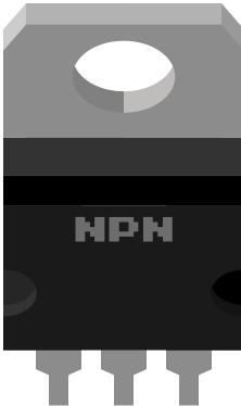
An NPN Power Transistor is a type of bipolar junction transistor (BJT) that uses an n-type material for both the emitter and collector, with a p-type material for the base. This configuration allows the transistor to amplify current and switch electronic signals effectively. Due to its ability to handle high currents and voltages, the NPN Power Transistor is widely used in power applications such as motor control, power amplifiers, and switching circuits.
Explore Projects Built with npn-Powertransistor
 Open Project in Cirkit Designer
 Open Project in Cirkit Designer
 Open Project in Cirkit Designer
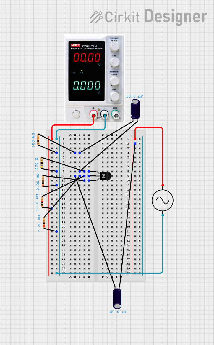 Open Project in Cirkit Designer
Explore Projects Built with npn-Powertransistor
Open Project in Cirkit DesignerOpen Project in Cirkit DesignerOpen Project in Cirkit DesignerOpen Project in Cirkit DesignerCommon Applications:
- Motor drivers and control circuits
- Power amplifiers in audio and RF systems
- Voltage regulation and power supply circuits
- High-speed switching in digital circuits
Technical Specifications
Below are the general technical specifications for a typical NPN Power Transistor. Note that specific values may vary depending on the exact model.
| Parameter | Value |
|---|---|
| Maximum Collector-Emitter Voltage (VCE) | 60V to 1200V (varies by model) |
| Maximum Collector Current (IC) | 5A to 50A (varies by model) |
| Maximum Power Dissipation (PD) | 50W to 300W |
| Current Gain (hFE) | 20 to 200 |
| Transition Frequency (fT) | 1 MHz to 30 MHz |
| Operating Temperature Range | -55°C to +150°C |
Pin Configuration
The NPN Power Transistor typically has three pins: Collector (C), Base (B), and Emitter (E). Below is the pinout description:
| Pin | Name | Description |
|---|---|---|
| 1 | Collector | The terminal through which the main current flows from the load to the emitter. |
| 2 | Base | The control terminal that regulates the flow of current between collector and emitter. |
| 3 | Emitter | The terminal through which current exits the transistor. |
Usage Instructions
How to Use the NPN Power Transistor in a Circuit
Biasing the Transistor:
- Apply a small current to the base pin to control a larger current flowing between the collector and emitter.
- Ensure the base-emitter voltage (VBE) is typically around 0.7V for silicon-based transistors.
Connecting the Load:
- Connect the load (e.g., motor, LED, or resistor) in series with the collector pin.
- The emitter pin is usually connected to ground in an NPN configuration.
Base Resistor:
- Use a resistor in series with the base pin to limit the base current and prevent damage to the transistor.
- Calculate the base resistor value using the formula:
[ R_B = \frac{V_{IN} - V_{BE}}{I_B} ]
where ( I_B = \frac{I_C}{h_{FE}} ).
Heat Dissipation:
- Use a heatsink if the transistor is expected to dissipate significant power to prevent overheating.
Example Circuit with Arduino UNO
Below is an example of using an NPN Power Transistor to control a DC motor with an Arduino UNO.
Circuit Description:
- The transistor acts as a switch to control the motor.
- A PWM signal from the Arduino controls the base of the transistor.
Code Example:
// Arduino code to control a DC motor using an NPN Power Transistor
const int motorPin = 9; // PWM pin connected to the base of the transistor

void setup() {
  pinMode(motorPin, OUTPUT); // Set motorPin as an output
}

void loop() {
  analogWrite(motorPin, 128); // Set motor speed to 50% (PWM value: 128 out of 255)
  delay(5000); // Run motor for 5 seconds

  analogWrite(motorPin, 0); // Turn off the motor
  delay(5000); // Wait for 5 seconds before restarting
}
Important Considerations:
- Voltage and Current Ratings: Ensure the transistor's voltage and current ratings exceed the requirements of your circuit.
- Base Drive Current: Provide sufficient base current to fully saturate the transistor for switching applications.
- Protection Diodes: Use a flyback diode across inductive loads (e.g., motors) to protect the transistor from voltage spikes.
Troubleshooting and FAQs
Common Issues and Solutions
Transistor Overheating:
- Cause: Excessive power dissipation or insufficient heat sinking.
- Solution: Use a heatsink or choose a transistor with a higher power rating.
Motor Not Running:
- Cause: Insufficient base current or incorrect wiring.
- Solution: Check the base resistor value and ensure proper connections.
Low Current Gain:
- Cause: Operating the transistor outside its optimal range.
- Solution: Verify the transistor's hFE and ensure the base current is adequate.
Voltage Drop Across the Transistor:
- Cause: The transistor is not fully saturated.
- Solution: Increase the base current to drive the transistor into saturation.
FAQs
Q1: Can I use an NPN Power Transistor for AC signals?
A1: Yes, NPN Power Transistors can amplify or switch AC signals, but additional circuitry (e.g., biasing and coupling capacitors) may be required.
Q2: How do I choose the right NPN Power Transistor for my application?
A2: Consider the voltage, current, and power requirements of your circuit. Ensure the transistor's ratings exceed these values with a safety margin.
Q3: What is the difference between a standard NPN transistor and an NPN Power Transistor?
A3: NPN Power Transistors are designed to handle higher currents and voltages, making them suitable for power applications, whereas standard NPN transistors are used for low-power applications.
Q4: Do I always need a heatsink for an NPN Power Transistor?
A4: Not always. A heatsink is only necessary if the transistor dissipates significant power and exceeds its safe operating temperature.
This concludes the documentation for the NPN Power Transistor.