How to Use Seeed Studio ePaper Breakout Board: Examples, Pinouts, and Specs
Introduction
The Seeed Studio ePaper Breakout Board is a versatile interface designed to work seamlessly with ePaper displays. It enables low-power, high-contrast visual output, making it ideal for applications such as digital signage, IoT devices, electronic shelf labels, and more. This breakout board simplifies the integration of ePaper technology into your projects by providing an easy-to-use interface and compatibility with popular microcontrollers like Arduino and Raspberry Pi.
ePaper displays are known for their ultra-low power consumption and excellent readability in various lighting conditions, including direct sunlight. The Seeed Studio ePaper Breakout Board is an essential tool for developers and hobbyists looking to leverage these benefits in their designs.
Explore Projects Built with Seeed Studio ePaper Breakout Board


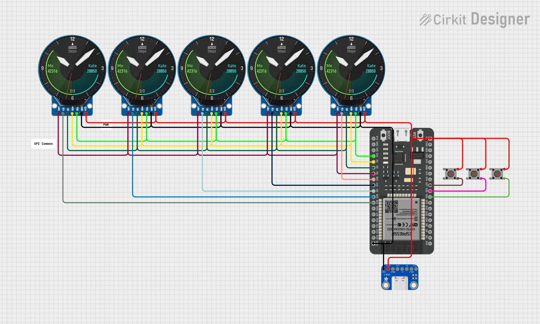
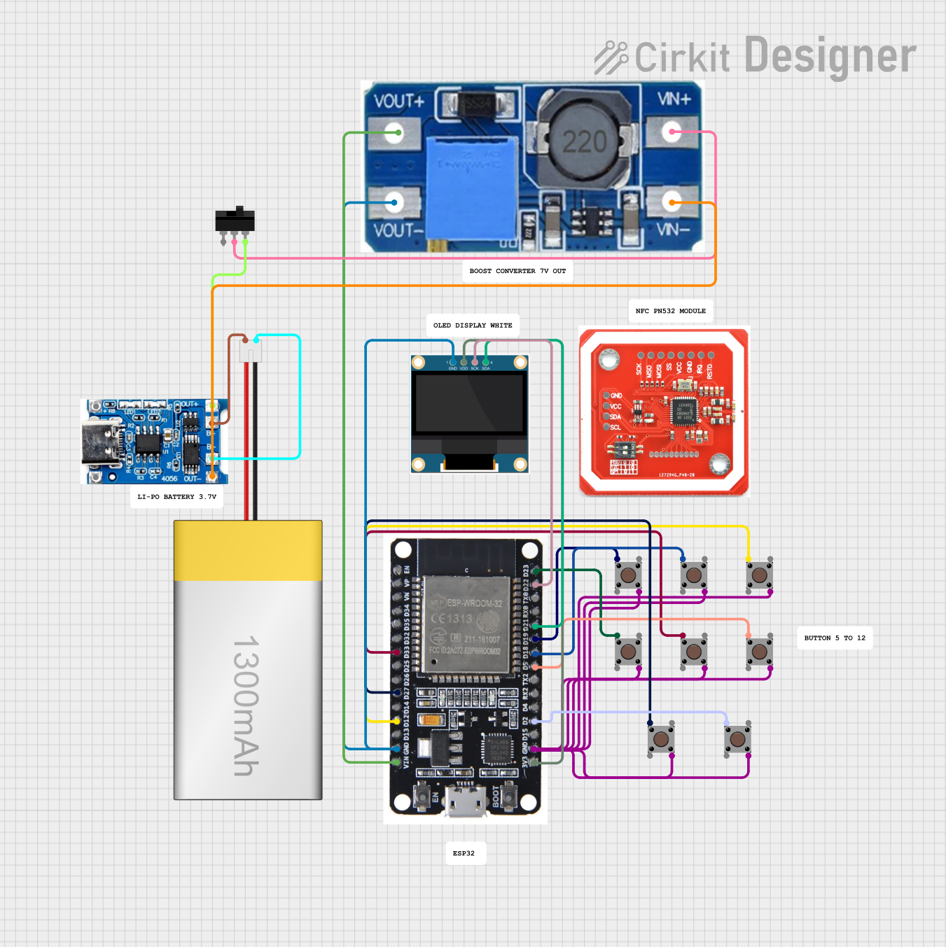
Explore Projects Built with Seeed Studio ePaper Breakout Board
Technical Specifications
Below are the key technical details and pin configuration for the Seeed Studio ePaper Breakout Board:
Key Technical Details
| Parameter | Specification |
|---|---|
| Supply Voltage | 3.3V or 5V |
| Communication Interface | SPI |
| Supported ePaper Sizes | 1.54", 2.13", 2.9", 4.2", and others |
| Power Consumption | Ultra-low (depends on ePaper display) |
| Operating Temperature | -20°C to 70°C |
| Dimensions | 40mm x 20mm x 5mm |
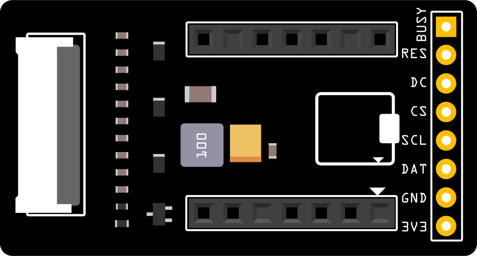
Pin Configuration and Descriptions
| Pin Name | Pin Type | Description |
|---|---|---|
| VCC | Power | Power supply input (3.3V or 5V) |
| GND | Ground | Ground connection |
| DIN | Input | SPI data input (MOSI) |
| CLK | Input | SPI clock input |
| CS | Input | Chip select signal for SPI communication |
| DC | Input | Data/Command control signal |
| RST | Input | Reset signal for the ePaper display |
| BUSY | Output | Busy signal from the ePaper display (indicates when the display is updating) |
Usage Instructions
How to Use the Component in a Circuit
- Power Supply: Connect the VCC pin to a 3.3V or 5V power source, depending on your microcontroller. Connect the GND pin to the ground.
- SPI Communication: Connect the SPI pins (DIN, CLK, CS) to the corresponding SPI pins on your microcontroller.
- Control Signals: Connect the DC, RST, and BUSY pins to GPIO pins on your microcontroller for proper control of the ePaper display.
- ePaper Display: Attach a compatible ePaper display to the breakout board using the provided connector.
Important Considerations and Best Practices
- Ensure the power supply voltage matches the requirements of your microcontroller and ePaper display.
- Use level shifters if your microcontroller operates at 5V and the ePaper display requires 3.3V logic levels.
- Avoid frequent updates to the ePaper display, as it is designed for static or infrequent changes to conserve power.
- Handle the ePaper display carefully to avoid damage to the delicate screen.
Example Code for Arduino UNO
Below is an example of how to use the Seeed Studio ePaper Breakout Board with an Arduino UNO and a 2.9" ePaper display:
#include <GxEPD2_BW.h> // Include the ePaper library

// Define the ePaper display type and pins
#define CS_PIN 10   // Chip select pin
#define DC_PIN 9    // Data/Command pin
#define RST_PIN 8   // Reset pin
#define BUSY_PIN 7  // Busy pin

// Create an instance of the ePaper display
GxEPD2_BW<GxEPD2_290, GxEPD2_290::HEIGHT> display(GxEPD2_290(CS_PIN, DC_PIN, RST_PIN, BUSY_PIN));

void setup() {
  // Initialize serial communication for debugging
  Serial.begin(115200);
  Serial.println("Initializing ePaper display...");

  // Initialize the ePaper display
  display.init();
  display.setRotation(1); // Set display rotation (0-3)

  // Clear the display
  display.fillScreen(GxEPD_WHITE);
  display.display();

  // Display a message
  display.setTextColor(GxEPD_BLACK);
  display.setCursor(10, 20); // Set text position
  display.setTextSize(2);    // Set text size
  display.print("Hello, ePaper!");
  display.display();         // Update the display
}

void loop() {
  // The ePaper display does not require constant refreshing
  // Add your logic here if needed
}
Notes:
- Install the
GxEPD2library from the Arduino Library Manager before using the code. - Adjust the pin definitions and display type in the code to match your specific setup.
Troubleshooting and FAQs
Common Issues and Solutions
The display does not turn on or update:
- Verify that the power supply voltage matches the requirements of the breakout board and ePaper display.
- Check all connections, especially the SPI and control signal pins.
- Ensure the
GxEPD2library is correctly installed and the display type is properly defined in the code.
The display shows artifacts or incomplete updates:
- Ensure the BUSY pin is correctly connected and monitored in the code.
- Avoid updating the display too frequently, as ePaper technology requires time to refresh.
The display remains blank:
- Double-check the wiring and ensure the correct pins are defined in the code.
- Perform a reset by toggling the RST pin in the code or manually.
FAQs
Q: Can I use this breakout board with a Raspberry Pi?
A: Yes, the breakout board is compatible with Raspberry Pi. You can use the SPI interface and appropriate libraries (e.g., python-eink) to control the ePaper display.
Q: What is the typical power consumption of the breakout board?
A: The power consumption is extremely low, as ePaper displays only consume power during updates. The exact value depends on the size and type of the ePaper display used.
Q: Can I use this breakout board with a 5V microcontroller?
A: Yes, but you may need level shifters to ensure compatibility with 3.3V logic levels required by the ePaper display.
By following this documentation, you can successfully integrate the Seeed Studio ePaper Breakout Board into your projects and take advantage of its low-power, high-contrast display capabilities.