Cirkit Designer Logo
Cirkit Designer
Your all-in-one circuit design IDE
Home / 
Component Documentation

How to Use PoE PSU 48V DC: Examples, Pinouts, and Specs

Image of PoE PSU 48V DC
Cirkit Designer LogoDesign with PoE PSU 48V DC in Cirkit Designer

Introduction

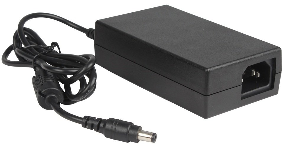
The Power over Ethernet (PoE) Power Supply Unit (PSU) 48V DC is an electronic component designed to deliver power to PoE-enabled devices through Ethernet cabling. This allows for the transmission of both power and data over a single network cable, simplifying wiring and reducing installation costs. Common applications include powering IP cameras, wireless access points, VoIP phones, and other network devices that support PoE.

Explore Projects Built with PoE PSU 48V DC

Use Cirkit Designer to design, explore, and prototype these projects online. Some projects support real-time simulation. Click "Open Project" to start designing instantly!
Optiplex Micro and PoE Camera Surveillance System with Ethernet Switching
Image of Engine Mounts Wiring: A project utilizing PoE PSU 48V DC in a practical application
This circuit describes a networked system where an Optiplex Micro computer is powered by a PC Power Supply and connected to a PC Screen via HDMI for display output. The computer is networked through an Ethernet Switch, which also connects to two PoE Cameras and a Toyopuc PLC. The Ethernet Switch is powered by a PoE PSU 48V DC, and all AC-powered devices are connected to a common 220V AC source.
Cirkit Designer LogoOpen Project in Cirkit Designer
24V Pushbutton Control Interface with 40-Pin Connector
Image of 4 på rad: A project utilizing PoE PSU 48V DC in a practical application
This circuit consists of a 24V power supply unit (PSU) connected to four pushbuttons. Each pushbutton is wired such that pressing it will send a 24V signal to a corresponding general-purpose input (GP In) on a 40-pin connector. The common return path for the pushbuttons is connected to the 0V of the PSU, which is also connected to the common (Com) for input pins on the 40-pin connector, completing the circuit for each button press.
Cirkit Designer LogoOpen Project in Cirkit Designer
Battery-Powered UPS with Step-Down Buck Converter and BMS
Image of Mini ups: A project utilizing PoE PSU 48V DC in a practical application
This circuit is a power management system that steps down a 240V AC input to a lower DC voltage using a buck converter, which then powers a 40W UPS. The UPS is controlled by a rocker switch and is backed up by a battery management system (BMS) connected to three 3.7V batteries in series, ensuring continuous power supply.
Cirkit Designer LogoOpen Project in Cirkit Designer
ESP32-Based Wi-Fi Controlled 24V Input/Output Interface Module
Image of ESP32 4 på rad: A project utilizing PoE PSU 48V DC in a practical application
This circuit uses an ESP32 microcontroller to interface with a 3.3V PNP to 24V NPN photoelectric isolation module, which in turn connects to a 40-pin connector for general-purpose input and output. The 24V power supply provides the necessary voltage for the isolation module and the 40-pin connector, enabling the ESP32 to control and monitor high-voltage signals safely.
Cirkit Designer LogoOpen Project in Cirkit Designer

Explore Projects Built with PoE PSU 48V DC

Use Cirkit Designer to design, explore, and prototype these projects online. Some projects support real-time simulation. Click "Open Project" to start designing instantly!
Image of Engine Mounts Wiring: A project utilizing PoE PSU 48V DC in a practical application
Optiplex Micro and PoE Camera Surveillance System with Ethernet Switching
This circuit describes a networked system where an Optiplex Micro computer is powered by a PC Power Supply and connected to a PC Screen via HDMI for display output. The computer is networked through an Ethernet Switch, which also connects to two PoE Cameras and a Toyopuc PLC. The Ethernet Switch is powered by a PoE PSU 48V DC, and all AC-powered devices are connected to a common 220V AC source.
Cirkit Designer LogoOpen Project in Cirkit Designer
Image of 4 på rad: A project utilizing PoE PSU 48V DC in a practical application
24V Pushbutton Control Interface with 40-Pin Connector
This circuit consists of a 24V power supply unit (PSU) connected to four pushbuttons. Each pushbutton is wired such that pressing it will send a 24V signal to a corresponding general-purpose input (GP In) on a 40-pin connector. The common return path for the pushbuttons is connected to the 0V of the PSU, which is also connected to the common (Com) for input pins on the 40-pin connector, completing the circuit for each button press.
Cirkit Designer LogoOpen Project in Cirkit Designer
Image of Mini ups: A project utilizing PoE PSU 48V DC in a practical application
Battery-Powered UPS with Step-Down Buck Converter and BMS
This circuit is a power management system that steps down a 240V AC input to a lower DC voltage using a buck converter, which then powers a 40W UPS. The UPS is controlled by a rocker switch and is backed up by a battery management system (BMS) connected to three 3.7V batteries in series, ensuring continuous power supply.
Cirkit Designer LogoOpen Project in Cirkit Designer
Image of ESP32 4 på rad: A project utilizing PoE PSU 48V DC in a practical application
ESP32-Based Wi-Fi Controlled 24V Input/Output Interface Module
This circuit uses an ESP32 microcontroller to interface with a 3.3V PNP to 24V NPN photoelectric isolation module, which in turn connects to a 40-pin connector for general-purpose input and output. The 24V power supply provides the necessary voltage for the isolation module and the 40-pin connector, enabling the ESP32 to control and monitor high-voltage signals safely.
Cirkit Designer LogoOpen Project in Cirkit Designer

Technical Specifications

General Specifications

Parameter Value Description
Output Voltage 48V DC The DC voltage supplied to the device.
Output Current Varies Maximum current the PSU can provide.
Power Rating Varies Total power output capacity.
PoE Standard IEEE 802.3af/at Compatibility with PoE standards.
Operating Temperature -10°C to +45°C Suitable temperature range for operation.

Pin Configuration and Descriptions

Pin Number Name Description
1 V+ Positive voltage output (48V DC)
2 V- Ground reference for the voltage output
3 DATA+ Data pair positive (if applicable)
4 DATA- Data pair negative (if applicable)
5 LED+ Anode for status LED (if present)
6 LED- Cathode for status LED (if present)

Note: The actual pinout may vary depending on the specific model and manufacturer. Always refer to the manufacturer's datasheet for exact pin configuration.

Usage Instructions

Integration into a Circuit

  1. Connection to PoE Device: Connect the V+ and V- pins to the power input of the PoE-enabled device, ensuring correct polarity.
  2. Data Connection (if applicable): If the PSU also carries data, connect DATA+ and DATA- to the respective data input pins on the device.
  3. Status LED (if present): Connect LED+ and LED- to the status LED pins if you wish to have a visual indicator of the PSU status.

Best Practices

  • Cable Quality: Use high-quality Ethernet cables to ensure reliable power and data transmission.
  • Overload Protection: Ensure the connected device does not exceed the PSU's current and power ratings.
  • Ventilation: Provide adequate ventilation around the PSU to prevent overheating.
  • Compliance: Use the PSU with devices that comply with the same PoE standards (IEEE 802.3af/at).

Troubleshooting and FAQs

Common Issues

  • No Power to Device: Check connections for proper polarity and ensure the cable is not damaged.
  • Intermittent Power: Verify that the PSU and device are not overheating and that the cable quality is adequate.
  • Device Not Recognizing Power: Ensure the device is PoE-compatible and that the PSU meets the required PoE standard.

FAQs

Q: Can I use this PSU with non-PoE devices? A: No, this PSU is designed for PoE-enabled devices only.

Q: What is the maximum cable length I can use with this PSU? A: The maximum recommended length for Ethernet cables with PoE is 100 meters.

Q: Can I daisy-chain multiple PoE devices with this PSU? A: Daisy-chaining is not recommended as it may exceed the PSU's power capacity and violate PoE standards.

Q: Is this PSU compatible with all PoE standards? A: This PSU is compatible with IEEE 802.3af/at standards. Check your device's specifications to ensure compatibility.

Example Code for Arduino UNO

This section provides an example of how to control a PoE-powered device with an Arduino UNO. The code demonstrates a simple on/off toggle for a PoE-powered LED light.

// Define the control pin for the PoE PSU
const int poeControlPin = 2;

void setup() {
  // Initialize the control pin as an output
  pinMode(poeControlPin, OUTPUT);
}

void loop() {
  // Turn on the PoE-powered device
  digitalWrite(poeControlPin, HIGH);
  delay(1000); // Wait for 1 second
  
  // Turn off the PoE-powered device
  digitalWrite(poeControlPin, LOW);
  delay(1000); // Wait for 1 second
}

Note: This example assumes that the Arduino UNO controls a relay or similar device that switches the PoE PSU on and off. The Arduino itself cannot directly switch the 48V DC power.

Remember to consult the datasheet and technical resources provided by the manufacturer for the most accurate and specific information regarding the PoE PSU 48V DC component.