How to Use PNOZ S4: Examples, Pinouts, and Specs
Introduction
The PNOZ S4 is a safety relay designed for monitoring safety circuits in machinery. It provides reliable safety functions such as emergency stop, safety gates, and light curtains, ensuring compliance with safety standards in industrial applications. This component is widely used in industrial automation to enhance operator safety and protect equipment by ensuring that safety-critical operations are performed reliably.
Explore Projects Built with PNOZ S4


Explore Projects Built with PNOZ S4
Common Applications and Use Cases
- Emergency stop monitoring in industrial machinery
- Safety gate monitoring for restricted areas
- Light curtain integration for hazardous zones
- Two-hand control systems for press machines
- General safety circuit monitoring in automated systems
Technical Specifications
Key Technical Details
| Parameter | Specification |
|---|---|
| Supply Voltage | 24 V DC / 24 V AC |
| Power Consumption | Approx. 2.5 W |
| Safety Outputs | 2 NO (Normally Open) relay outputs |
| Auxiliary Outputs | 1 NC (Normally Closed) relay output |
| Switching Capacity | 6 A at 250 V AC / 24 V DC |
| Response Time | ≤ 20 ms |
| Operating Temperature | -10°C to +55°C |
| Dimensions (W x H x D) | 22.5 mm x 100 mm x 120 mm |
| Mounting | DIN rail |
| Standards Compliance | EN ISO 13849-1, EN 62061, IEC 61508 |
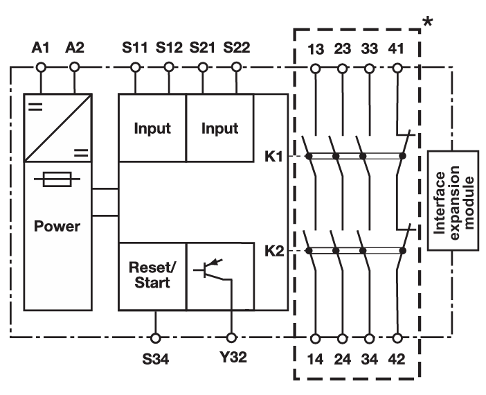
Pin Configuration and Descriptions
| Pin Number | Label | Description |
|---|---|---|
| 1 | A1 | Positive supply voltage (24 V DC/AC) |
| 2 | A2 | Negative supply voltage (0 V) |
| 3 | S11 | Input for safety circuit (channel 1) |
| 4 | S12 | Input for safety circuit (channel 2) |
| 5 | S21 | Feedback loop input |
| 6 | S22 | Feedback loop input |
| 7 | 13 | Safety output 1 (NO contact) |
| 8 | 14 | Safety output 1 (NO contact) |
| 9 | 23 | Safety output 2 (NO contact) |
| 10 | 24 | Safety output 2 (NO contact) |
| 11 | 31 | Auxiliary output (NC contact) |
| 12 | 32 | Auxiliary output (NC contact) |
Usage Instructions
How to Use the PNOZ S4 in a Circuit
- Power Supply Connection: Connect the positive terminal of the 24 V DC/AC power supply to pin A1 and the negative terminal to pin A2.
- Safety Circuit Inputs: Connect the safety devices (e.g., emergency stop button, safety gate switch) to pins S11 and S12. Ensure proper wiring for redundancy.
- Feedback Loop: If required, connect the feedback loop to pins S21 and S22 to monitor external contactors or relays.
- Safety Outputs: Use the safety outputs (pins 13-14 and 23-24) to control actuators or other devices that need to be de-energized in case of a fault.
- Auxiliary Output: Connect the auxiliary output (pins 31-32) to monitor the status of the safety relay.
Important Considerations and Best Practices
- Ensure that the wiring complies with relevant safety standards and regulations.
- Use appropriate fuses or circuit breakers to protect the relay and connected devices.
- Regularly test the safety circuit to verify proper operation.
- Avoid exposing the relay to excessive vibration, moisture, or temperatures outside the specified range.
- For redundancy, always use both safety channels (S11 and S12) in your circuit design.
Example: Connecting to an Arduino UNO
While the PNOZ S4 is primarily used in industrial applications, it can be interfaced with an Arduino UNO for educational or prototyping purposes. Below is an example of how to monitor the safety output using an Arduino:
// Example code to monitor the safety output of the PNOZ S4 using Arduino UNO

const int safetyOutputPin = 2; // Connect PNOZ S4 safety output (e.g., pin 13) to Arduino pin 2
const int ledPin = 13;         // Built-in LED on Arduino to indicate safety status

void setup() {
  pinMode(safetyOutputPin, INPUT); // Set safety output pin as input
  pinMode(ledPin, OUTPUT);         // Set LED pin as output
  digitalWrite(ledPin, LOW);       // Turn off LED initially
  Serial.begin(9600);             // Initialize serial communication
}

void loop() {
  int safetyStatus = digitalRead(safetyOutputPin); // Read safety output status

  if (safetyStatus == HIGH) {
    // Safety circuit is active
    digitalWrite(ledPin, HIGH); // Turn on LED
    Serial.println("Safety circuit is active.");
  } else {
    // Safety circuit is inactive
    digitalWrite(ledPin, LOW);  // Turn off LED
    Serial.println("Safety circuit is inactive!");
  }

  delay(500); // Wait for 500 ms before next reading
}
Note: Ensure proper isolation between the PNOZ S4 and Arduino using optocouplers or relays to avoid damage to the Arduino.
Troubleshooting and FAQs
Common Issues and Solutions
Issue: The safety relay does not power on.
- Solution: Verify the power supply voltage (24 V DC/AC) and ensure correct polarity on pins A1 and A2.
Issue: Safety outputs do not activate.
- Solution: Check the wiring of the safety inputs (S11 and S12) and ensure the safety devices are functioning correctly. Verify the feedback loop if used.
Issue: Auxiliary output does not change state.
- Solution: Ensure the safety relay is operating correctly and that the auxiliary output is wired properly.
Issue: The relay trips unexpectedly.
- Solution: Inspect the safety devices and wiring for faults or intermittent connections. Ensure the operating environment meets the specified conditions.
FAQs
Q: Can the PNOZ S4 be used with a 12 V power supply?
A: No, the PNOZ S4 requires a 24 V DC/AC power supply for proper operation.Q: How often should the safety circuit be tested?
A: It is recommended to test the safety circuit regularly, as specified by your local safety regulations or the machinery manufacturer.Q: Can I use only one safety input channel (S11 or S12)?
A: For redundancy and compliance with safety standards, both channels should be used.Q: What is the purpose of the feedback loop?
A: The feedback loop monitors external contactors or relays to ensure they are functioning correctly and have not welded or failed.
By following this documentation, users can effectively integrate and troubleshoot the PNOZ S4 safety relay in their safety-critical applications.