
How to Use DB25: Examples, Pinouts, and Specs
 Design with DB25 in Cirkit Designer
Introduction
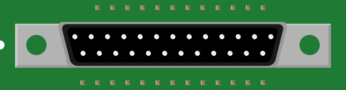
The DB25 is a 25-pin D-subminiature connector widely used for parallel and serial communication. It is a versatile and robust connector that has been a standard in older computer systems and peripheral devices. The DB25 connector is available in both male and female configurations and is commonly used for RS-232 serial communication, parallel printer ports, and other legacy interfaces.
Explore Projects Built with DB25
 Open Project in Cirkit Designer
 Open Project in Cirkit Designer
 Open Project in Cirkit Designer
 Open Project in Cirkit Designer
Explore Projects Built with DB25
Open Project in Cirkit DesignerOpen Project in Cirkit DesignerOpen Project in Cirkit DesignerOpen Project in Cirkit DesignerCommon Applications and Use Cases
- RS-232 serial communication for data transfer between computers and peripherals.
- Parallel communication for printers and other legacy devices.
- Industrial control systems and test equipment.
- Custom cable assemblies for data and signal transmission.
Technical Specifications
Key Technical Details
- Manufacturer: Generic
- Part ID: DB25
- Connector Type: D-subminiature, 25-pin
- Gender: Male or Female (depending on configuration)
- Pin Count: 25
- Contact Material: Gold-plated or tin-plated contacts (varies by manufacturer)
- Housing Material: Metal or plastic shell with strain relief options
- Mounting Style: Panel mount or cable mount
- Voltage Rating: Typically up to 250V
- Current Rating: Typically up to 5A per pin
- Operating Temperature: -55°C to +105°C
Pin Configuration and Descriptions
The DB25 connector has 25 pins arranged in two rows: 13 pins in the top row and 12 pins in the bottom row. Below is the standard pinout for RS-232 serial communication:
| Pin Number | Signal Name | Description |
|---|---|---|
| 1 | Shield Ground (GND) | Protective ground for shielding |
| 2 | Transmit Data (TXD) | Data transmitted from the device |
| 3 | Receive Data (RXD) | Data received by the device |
| 4 | Data Terminal Ready (DTR) | Indicates device is ready to communicate |
| 5 | Signal Ground (GND) | Common ground for signals |
| 6 | Data Set Ready (DSR) | Indicates readiness of connected device |
| 7 | Request to Send (RTS) | Requests permission to send data |
| 8 | Clear to Send (CTS) | Indicates permission to send data |
| 9 | Ring Indicator (RI) | Indicates incoming call (modem use) |
| 10-25 | Reserved/Custom Use | Varies depending on application |
Note: The pinout may vary depending on the specific application (e.g., parallel communication). Always refer to the device's datasheet or manual for the correct pinout.
Usage Instructions
How to Use the DB25 in a Circuit
- Identify the Pinout: Determine the required pin configuration based on your application (e.g., RS-232 or parallel communication).
- Connect the Wires: Solder or crimp the wires to the appropriate pins of the DB25 connector. Use a cable with shielding if noise immunity is required.
- Mount the Connector: Secure the DB25 connector to a panel or cable housing using screws or clips.
- Verify Connections: Use a multimeter to check for continuity and ensure proper connections.
- Connect to Devices: Plug the DB25 connector into the corresponding port on the device.
Important Considerations and Best Practices
- Shielding: Use shielded cables to minimize electromagnetic interference (EMI) in noisy environments.
- Strain Relief: Ensure proper strain relief to prevent damage to the wires and connector.
- Compatibility: Verify that the DB25 connector matches the port type (male or female) and pinout of the device.
- Legacy Support: Be aware that DB25 connectors are primarily used in legacy systems and may require adapters for modern devices.
Example: Connecting DB25 to Arduino UNO
While the DB25 is not directly compatible with Arduino UNO, it can be used for serial communication with additional circuitry. Below is an example of interfacing a DB25 connector for RS-232 communication:
#include <SoftwareSerial.h>

// Define RX and TX pins for SoftwareSerial
SoftwareSerial mySerial(10, 11); // RX = pin 10, TX = pin 11

void setup() {
  // Start the hardware serial communication
  Serial.begin(9600);
  // Start the software serial communication
  mySerial.begin(9600);
  Serial.println("DB25 RS-232 Communication Initialized");
}

void loop() {
  // Check if data is available from the DB25 device
  if (mySerial.available()) {
    char received = mySerial.read();
    Serial.print("Received: ");
    Serial.println(received);
  }

  // Send data to the DB25 device
  if (Serial.available()) {
    char toSend = Serial.read();
    mySerial.write(toSend);
    Serial.print("Sent: ");
    Serial.println(toSend);
  }
}
Note: Use an RS-232 to TTL level shifter module to interface the DB25 connector with the Arduino UNO, as RS-232 signals operate at higher voltage levels than the Arduino's logic levels.
Troubleshooting and FAQs
Common Issues and Solutions
No Communication Between Devices
- Cause: Incorrect pinout or wiring.
- Solution: Double-check the pinout and ensure proper connections.
Signal Interference or Noise
- Cause: Lack of shielding in the cable.
- Solution: Use a shielded cable and connect the shield to ground.
Loose Connections
- Cause: Improper mounting or strain relief.
- Solution: Secure the connector with screws and use strain relief clamps.
Incompatible Connector Gender
- Cause: Mismatch between male and female connectors.
- Solution: Use a gender changer or the correct connector type.
FAQs
Q: Can the DB25 connector be used for modern devices?
A: While primarily used in legacy systems, the DB25 can still be used with adapters or converters for modern devices.Q: What is the difference between male and female DB25 connectors?
A: Male connectors have pins, while female connectors have sockets. Ensure compatibility with the device's port.Q: How do I identify the pin numbers on a DB25 connector?
A: Pin numbers are typically labeled on the connector or can be identified using a pinout diagram.Q: Can I use the DB25 for custom applications?
A: Yes, the DB25 is versatile and can be used for custom data and signal transmission projects.