Cirkit Designer Logo
Cirkit Designer
Your all-in-one circuit design IDE
Home / 
Component Documentation

How to Use Door MC-38: Examples, Pinouts, and Specs

Image of Door MC-38
Cirkit Designer LogoDesign with Door MC-38 in Cirkit Designer

Introduction

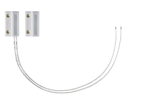
The Door MC-38 is a magnetic reed switch commonly used as a sensor for detecting the opening and closing of doors and windows. It is a simple, yet effective component for security systems, home automation, and other applications where it is necessary to monitor the status of an entry point.

Explore Projects Built with Door MC-38

Use Cirkit Designer to design, explore, and prototype these projects online. Some projects support real-time simulation. Click "Open Project" to start designing instantly!
Arduino Mega 2560-Controlled Stepper Motors with RFID Access and Traffic Light Indication
Image of Copy of test: A project utilizing Door MC-38 in a practical application
This circuit controls two 28BYJ-48 stepper motors using A4988 stepper motor driver carriers, interfaced with an Arduino Mega 2560 microcontroller. It features an RFID-RC522 module for RFID reading, a 16x4 LCD display with I2C interface for user interaction, and a piezo speaker for audio feedback. Additionally, there is a traffic light module controlled by the Arduino, and a 48V to 5V converter to step down voltage for the logic levels. The power supply provides 12V to the motor drivers and is connected to a standard power outlet.
Cirkit Designer LogoOpen Project in Cirkit Designer
RFID-Activated Traffic Light Controller with Auditory Feedback Using Arduino Mega
Image of test: A project utilizing Door MC-38 in a practical application
This circuit is designed to control two 28BYJ-48 stepper motors using A4988 stepper motor driver carriers, with an Arduino Mega 2560 as the central microcontroller. It includes an RFID-RC522 module for RFID reading, an LCD display for user interface, and a traffic light and piezo speaker for visual and audio signaling. The circuit is powered by a 12V 5A power supply, which is stepped down to 5V for logic level components, and it interfaces with a power outlet for AC to DC conversion.
Cirkit Designer LogoOpen Project in Cirkit Designer
ESP32-Based Automatic Cigarette Machine with Hall Sensors and Stepper Motors
Image of HK: A project utilizing Door MC-38 in a practical application
This circuit is an automated cigarette machine controlled by an ESP32 microcontroller. It interfaces with various sensors and actuators, including Hall sensors, IR sensors, pushbuttons, servos, stepper motors, and an RGB LED matrix, to automate the process of making cigarettes.
Cirkit Designer LogoOpen Project in Cirkit Designer
ESP32-Controlled Traffic Light and Multi-Motor Driver System
Image of Projeto final: A project utilizing Door MC-38 in a practical application
This circuit features an ESP32 microcontroller connected to a traffic light module and multiple DC motors via two L298N motor drivers. The ESP32 controls the traffic light states and motor operations, likely for a model intersection with moving parts. The circuit also includes MT3608 boost converters to step up the voltage from a 4 x AAA battery mount to the required levels for the motor drivers, and an MG996R servo motor controlled directly by the ESP32.
Cirkit Designer LogoOpen Project in Cirkit Designer

Explore Projects Built with Door MC-38

Use Cirkit Designer to design, explore, and prototype these projects online. Some projects support real-time simulation. Click "Open Project" to start designing instantly!
Image of Copy of test: A project utilizing Door MC-38 in a practical application
Arduino Mega 2560-Controlled Stepper Motors with RFID Access and Traffic Light Indication
This circuit controls two 28BYJ-48 stepper motors using A4988 stepper motor driver carriers, interfaced with an Arduino Mega 2560 microcontroller. It features an RFID-RC522 module for RFID reading, a 16x4 LCD display with I2C interface for user interaction, and a piezo speaker for audio feedback. Additionally, there is a traffic light module controlled by the Arduino, and a 48V to 5V converter to step down voltage for the logic levels. The power supply provides 12V to the motor drivers and is connected to a standard power outlet.
Cirkit Designer LogoOpen Project in Cirkit Designer
Image of test: A project utilizing Door MC-38 in a practical application
RFID-Activated Traffic Light Controller with Auditory Feedback Using Arduino Mega
This circuit is designed to control two 28BYJ-48 stepper motors using A4988 stepper motor driver carriers, with an Arduino Mega 2560 as the central microcontroller. It includes an RFID-RC522 module for RFID reading, an LCD display for user interface, and a traffic light and piezo speaker for visual and audio signaling. The circuit is powered by a 12V 5A power supply, which is stepped down to 5V for logic level components, and it interfaces with a power outlet for AC to DC conversion.
Cirkit Designer LogoOpen Project in Cirkit Designer
Image of HK: A project utilizing Door MC-38 in a practical application
ESP32-Based Automatic Cigarette Machine with Hall Sensors and Stepper Motors
This circuit is an automated cigarette machine controlled by an ESP32 microcontroller. It interfaces with various sensors and actuators, including Hall sensors, IR sensors, pushbuttons, servos, stepper motors, and an RGB LED matrix, to automate the process of making cigarettes.
Cirkit Designer LogoOpen Project in Cirkit Designer
Image of Projeto final: A project utilizing Door MC-38 in a practical application
ESP32-Controlled Traffic Light and Multi-Motor Driver System
This circuit features an ESP32 microcontroller connected to a traffic light module and multiple DC motors via two L298N motor drivers. The ESP32 controls the traffic light states and motor operations, likely for a model intersection with moving parts. The circuit also includes MT3608 boost converters to step up the voltage from a 4 x AAA battery mount to the required levels for the motor drivers, and an MG996R servo motor controlled directly by the ESP32.
Cirkit Designer LogoOpen Project in Cirkit Designer

Common Applications and Use Cases

  • Home and commercial security systems
  • Automated lighting control when doors are opened or closed
  • Monitoring access to restricted areas
  • DIY projects involving entry detection

Technical Specifications

Key Technical Details

  • Operating Voltage: Typically 100VDC
  • Maximum Switching Current: 0.5A
  • Maximum Carrying Current: 1.0A
  • Contact Type: Normally Open (NO)
  • Contact Resistance: <100 milliohms
  • Recommended Mounting Method: Screw or adhesive pad

Pin Configuration and Descriptions

The Door MC-38 does not have traditional pins but has two parts: the reed switch and the magnet. The reed switch has two wires for connection.

Wire Color Description
Red Connect to power
Black Connect to ground

Usage Instructions

How to Use the Component in a Circuit

  1. Mounting: Install the reed switch on the door frame and the magnet on the door itself, ensuring they are aligned when the door is closed.
  2. Wiring: Connect the red wire to the input of a digital pin on a microcontroller (e.g., Arduino) and the black wire to ground.
  3. Pull-up Resistor: Use an internal or external pull-up resistor to keep the input HIGH when the door is closed and the circuit is open.

Important Considerations and Best Practices

  • Alignment: Proper alignment of the magnet and switch is crucial for accurate detection.
  • Debouncing: Implement software debouncing to avoid false triggers due to mechanical vibrations.
  • Cable Length: Keep the wires as short as possible to minimize interference and voltage drop.

Example Code for Arduino UNO

// Define the pin connected to the Door MC-38
const int doorSensorPin = 2;

void setup() {
  // Set the door sensor pin as an input with an internal pull-up resistor
  pinMode(doorSensorPin, INPUT_PULLUP);
  // Initialize serial communication at 9600 bits per second
  Serial.begin(9600);
}

void loop() {
  // Read the state of the door sensor
  int doorState = digitalRead(doorSensorPin);

  // Check if the door is open (the reed switch is open and the input is HIGH)
  if (doorState == HIGH) {
    Serial.println("Door is open");
  } else {
    Serial.println("Door is closed");
  }

  // Delay for a bit to avoid spamming the serial output
  delay(500);
}

Troubleshooting and FAQs

Common Issues Users Might Face

  • Misalignment: The door sensor does not trigger when the door is opened or closed. Ensure the magnet and switch are properly aligned.
  • Wiring Issues: If the sensor is not responding, check all connections for proper contact and ensure there are no breaks in the wires.
  • False Triggers: If the sensor is triggering falsely, implement a debounce algorithm in your code.

Solutions and Tips for Troubleshooting

  • Test with a Multimeter: Use a multimeter to check for continuity when the door is closed. If there is no continuity, adjust the alignment or check the wiring.
  • Software Debounce: Implement a simple debounce function in your code to filter out noise.
  • Secure Mounting: Ensure that both the reed switch and magnet are securely mounted to prevent movement and misalignment.

FAQs

Q: Can the Door MC-38 be used outdoors? A: Yes, but it should be protected from the elements to prevent corrosion and damage.

Q: What is the maximum distance the magnet can be from the switch? A: The maximum operating gap is typically around 15-25mm, but it's best to keep it as close as possible for reliable operation.

Q: Can I connect multiple Door MC-38 switches to a single Arduino? A: Yes, you can connect multiple switches to different digital pins on the Arduino, just ensure each has its own pull-up resistor if not using the internal one.