How to Use MLX90640: Examples, Pinouts, and Specs
Introduction
The MLX90640 is a 32x24 pixel thermal imaging sensor designed for non-contact temperature measurement. It operates in the infrared spectrum, allowing it to detect temperature variations across a surface or object. With a wide temperature detection range of -40°C to 300°C, the MLX90640 is ideal for applications such as thermal monitoring, HVAC systems, robotics, and even human body temperature detection. Its compact design and high accuracy make it a popular choice for both industrial and consumer applications.
Explore Projects Built with MLX90640


Explore Projects Built with MLX90640
Technical Specifications
- Resolution: 32x24 pixels
- Temperature Range: -40°C to 300°C
- Field of View (FoV): Available in 55°x35° or 110°x75° models
- Accuracy: ±1°C (typical, for object temperatures between 0°C and 50°C)
- Supply Voltage: 3.3V
- Interface: I²C (Inter-Integrated Circuit)
- Frame Rate: Configurable, up to 64 Hz
- Operating Temperature: -40°C to 85°C
- Power Consumption: ~23mA (typical)
Pin Configuration and Descriptions
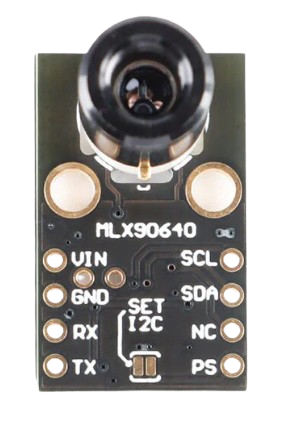
The MLX90640 is typically available in a breakout board format. Below is the pin configuration for a common MLX90640 breakout board:
| Pin | Name | Description |
|---|---|---|
| 1 | VCC | Power supply input (3.3V) |
| 2 | GND | Ground connection |
| 3 | SDA | I²C data line (connect to microcontroller's SDA pin) |
| 4 | SCL | I²C clock line (connect to microcontroller's SCL pin) |
| 5 | INT | Interrupt pin (optional, used for advanced configurations) |
| 6 | ADDR | I²C address selection pin (used to set the device's I²C address) |
Usage Instructions
How to Use the MLX90640 in a Circuit
- Power Supply: Connect the VCC pin to a 3.3V power source and the GND pin to ground.
- I²C Communication: Connect the SDA and SCL pins to the corresponding I²C pins on your microcontroller. Use pull-up resistors (typically 4.7kΩ) on the SDA and SCL lines if not already present on the breakout board.
- I²C Address: Configure the ADDR pin to set the I²C address. Refer to the breakout board's datasheet for address selection details.
- Interrupt Pin (Optional): If required, connect the INT pin to a GPIO pin on your microcontroller for advanced configurations.
Important Considerations and Best Practices
- Power Supply: Ensure a stable 3.3V power source. Using a higher voltage may damage the sensor.
- I²C Pull-Up Resistors: Verify if the breakout board includes pull-up resistors. If not, add external resistors to the SDA and SCL lines.
- Field of View: Choose the appropriate FoV model (55°x35° or 110°x75°) based on your application.
- Thermal Isolation: Avoid placing the sensor near heat sources or reflective surfaces to prevent inaccurate readings.
- Frame Rate: Higher frame rates increase power consumption. Use a lower frame rate for battery-powered applications.
Example Code for Arduino UNO
Below is an example of how to interface the MLX90640 with an Arduino UNO using the I²C protocol. This code uses the Adafruit MLX90640 library.
#include <Wire.h>
#include <Adafruit_MLX90640.h>

// Create an instance of the MLX90640 object
Adafruit_MLX90640 mlx;

// Define the frame buffer to store temperature data
float frame[32 * 24]; // 32x24 resolution

void setup() {
  Serial.begin(115200); // Initialize serial communication
  Wire.begin();         // Initialize I²C communication

  // Initialize the MLX90640 sensor
  if (!mlx.begin()) {
    Serial.println("MLX90640 not detected. Check wiring!");
    while (1); // Halt execution if sensor is not found
  }

  // Set the refresh rate to 8Hz (adjustable: 0.5Hz to 64Hz)
  mlx.setMode(MLX90640_INTERLEAVED);
  mlx.setRefreshRate(MLX90640_8_HZ);

  Serial.println("MLX90640 initialized successfully!");
}

void loop() {
  // Read temperature data into the frame buffer
  if (mlx.getFrame(frame)) {
    Serial.println("Temperature data:");
    for (int i = 0; i < 32 * 24; i++) {
      Serial.print(frame[i], 1); // Print temperature with 1 decimal place
      Serial.print(" ");
      if ((i + 1) % 32 == 0) {
        Serial.println(); // New line after every 32 pixels
      }
    }
    delay(125); // Delay to match the 8Hz refresh rate
  } else {
    Serial.println("Failed to read frame data!");
  }
}
Notes on the Code
- Install the Adafruit MLX90640 library via the Arduino Library Manager before running the code.
- Ensure the MLX90640 is connected to the correct I²C pins on the Arduino UNO (SDA = A4, SCL = A5).
- Adjust the refresh rate (
MLX90640_8_HZ) as needed for your application.
Troubleshooting and FAQs
Common Issues
Sensor Not Detected:
- Cause: Incorrect wiring or I²C address mismatch.
- Solution: Verify the connections and ensure the ADDR pin is configured correctly.
Inaccurate Temperature Readings:
- Cause: Sensor exposed to heat sources or reflective surfaces.
- Solution: Isolate the sensor from external heat sources and avoid reflective objects in its field of view.
I²C Communication Errors:
- Cause: Missing or incorrect pull-up resistors on SDA/SCL lines.
- Solution: Add 4.7kΩ pull-up resistors if not already present.
Frame Data Not Updating:
- Cause: Incorrect frame rate configuration.
- Solution: Ensure the frame rate matches the delay in your code.
FAQs
Can the MLX90640 detect human body temperature?
- Yes, the MLX90640 can accurately measure human body temperature. However, ensure proper calibration for medical-grade accuracy.
What is the maximum distance for temperature measurement?
- The effective distance depends on the object size and the sensor's FoV. For small objects, the sensor should be closer for accurate readings.
Can I use the MLX90640 with a 5V microcontroller?
- Yes, but you must use a logic level shifter to convert the 5V I²C signals to 3.3V.
How do I change the I²C address?
- The I²C address is configured using the ADDR pin. Refer to the breakout board's documentation for details.
By following this documentation, you can effectively integrate the MLX90640 into your projects and troubleshoot common issues.