
How to Use 5x7 pin board (all pins): Examples, Pinouts, and Specs
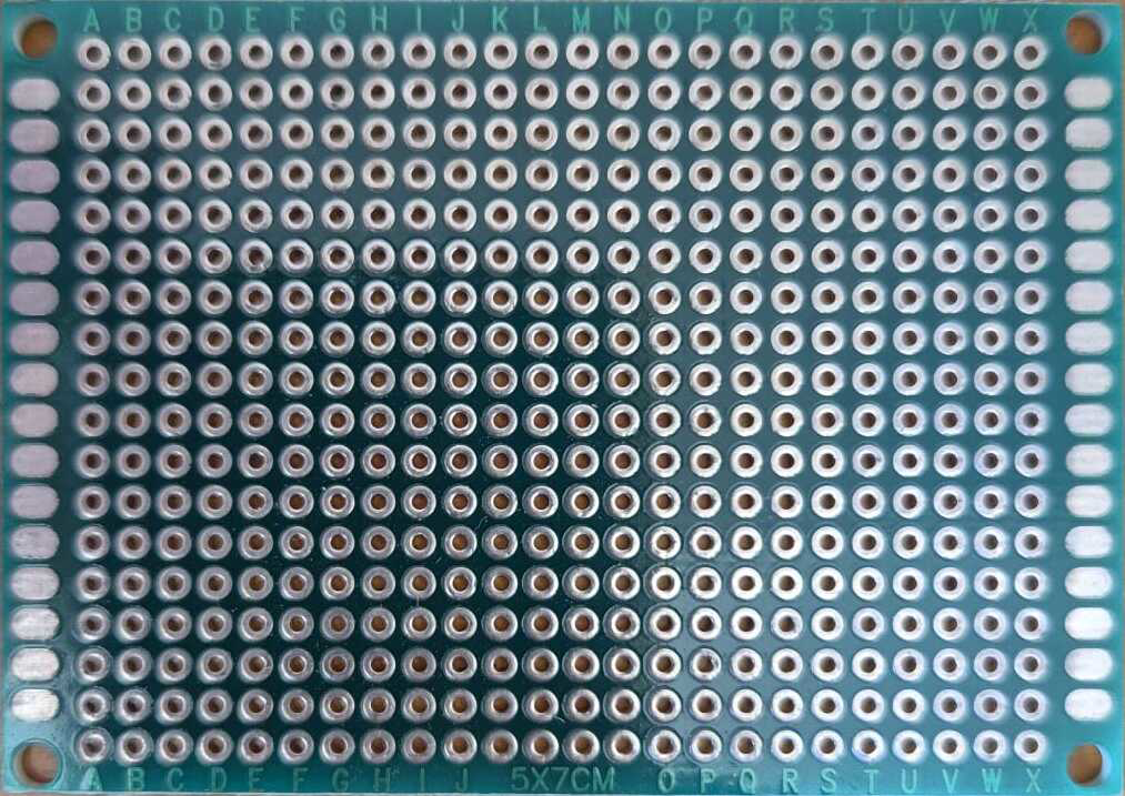
 Design with 5x7 pin board (all pins) in Cirkit Designer
Introduction
The 5x7 pin board is a versatile prototyping board designed for assembling and testing electronic circuits. It features a grid of 35 pins arranged in a 5x7 layout, providing a compact and organized platform for connecting components. This board is ideal for rapid prototyping, circuit experimentation, and small-scale development projects. Its pin grid allows for easy soldering or use with jumper wires, making it suitable for both beginners and experienced electronics enthusiasts.
Explore Projects Built with 5x7 pin board (all pins)
 Open Project in Cirkit Designer
 Open Project in Cirkit Designer
 Open Project in Cirkit Designer
 Open Project in Cirkit Designer
Explore Projects Built with 5x7 pin board (all pins)
Open Project in Cirkit DesignerOpen Project in Cirkit DesignerOpen Project in Cirkit DesignerOpen Project in Cirkit DesignerCommon Applications and Use Cases
- Prototyping and testing small electronic circuits
- Educational projects and learning circuit design
- Temporary or semi-permanent circuit assembly
- Connecting sensors, LEDs, and other components for Arduino or microcontroller projects
- Creating compact, modular circuit designs
Technical Specifications
The 5x7 pin board is a simple yet essential tool for prototyping. Below are its key technical details:
Key Specifications
| Parameter | Value |
|---|---|
| Dimensions | 5 rows x 7 columns (35 pins) |
| Pin Spacing | 2.54 mm (0.1 inch) standard |
| Material | FR4 or similar PCB material |
| Pin Type | Tinned through-hole pins |
| Compatibility | Breadboards, jumper wires, soldering |
| Maximum Voltage | 50V (typical, depends on use) |
| Maximum Current | 1A per pin (typical) |
Pin Configuration and Descriptions
The 5x7 pin board does not have predefined pin functions, as it is a general-purpose prototyping tool. However, the grid layout is as follows:
| Row/Column | Pin Count | Description |
|---|---|---|
| Rows | 5 | Horizontal rows for connections |
| Columns | 7 | Vertical columns for connections |
| Total Pins | 35 | Total available connection points |
Each pin is electrically isolated, allowing for flexible circuit design. Connections can be made using solder, jumper wires, or conductive traces.
Usage Instructions
How to Use the 5x7 Pin Board in a Circuit
- Plan Your Circuit Layout: Sketch your circuit design and determine how components will be placed on the board.
- Insert Components: Place components such as resistors, capacitors, ICs, or sensors into the pin holes.
- Make Connections:
- Use jumper wires for temporary connections.
- Solder components and wires for a more permanent setup.
- Test the Circuit: Connect the board to a power source and test the circuit functionality.
- Modify as Needed: Adjust connections or replace components as required.
Important Considerations and Best Practices
- Avoid Overloading Pins: Ensure that the current and voltage do not exceed the board's maximum ratings.
- Use Insulated Wires: To prevent short circuits, use insulated jumper wires or heat-shrink tubing for exposed connections.
- Plan for Heat Dissipation: If using high-power components, ensure proper heat dissipation to avoid damaging the board.
- Label Connections: For complex circuits, label connections to avoid confusion during troubleshooting.
- Clean Solder Joints: If soldering, ensure clean and secure joints to maintain reliable connections.
Example: Connecting an LED to an Arduino UNO
The 5x7 pin board can be used to prototype a simple LED circuit with an Arduino UNO. Below is an example:
Circuit Components
- 1x 5x7 pin board
- 1x LED
- 1x 220-ohm resistor
- Jumper wires
- Arduino UNO
Circuit Diagram
- Connect the LED's anode (longer leg) to one pin on the board.
- Connect the cathode (shorter leg) to a 220-ohm resistor, and then connect the resistor to the board's ground pin.
- Use a jumper wire to connect the LED's anode to Arduino pin 13.
- Connect the board's ground pin to the Arduino's GND pin.
Arduino Code
// Simple LED Blink Example
// This code blinks an LED connected to pin 13 of the Arduino UNO.
// Ensure the LED is connected via the 5x7 pin board.

void setup() {
  pinMode(13, OUTPUT); // Set pin 13 as an output pin
}

void loop() {
  digitalWrite(13, HIGH); // Turn the LED on
  delay(1000);            // Wait for 1 second
  digitalWrite(13, LOW);  // Turn the LED off
  delay(1000);            // Wait for 1 second
}
Troubleshooting and FAQs
Common Issues Users Might Face
Loose Connections:
- Problem: Components or wires are not securely connected to the board.
- Solution: Ensure all connections are tight. If soldering, check for cold solder joints.
Short Circuits:
- Problem: Adjacent pins are accidentally connected, causing a short circuit.
- Solution: Inspect the board for unintended connections and use insulated wires.
Overloaded Pins:
- Problem: Excessive current or voltage damages the board or components.
- Solution: Verify that the circuit operates within the board's maximum ratings.
Component Misplacement:
- Problem: Components are placed incorrectly, leading to circuit malfunction.
- Solution: Double-check the circuit diagram and component orientation.
FAQs
Q: Can I reuse the 5x7 pin board after soldering?
A: Yes, but desoldering components may damage the board or leave residue. For reusable setups, use jumper wires instead of soldering.
Q: Is the 5x7 pin board compatible with breadboards?
A: Yes, the 2.54 mm pin spacing matches standard breadboard layouts, allowing for easy integration.
Q: Can I use the 5x7 pin board for high-frequency circuits?
A: While it is possible, the board's design may introduce parasitic capacitance and inductance, which could affect high-frequency performance.
Q: How do I clean the board after soldering?
A: Use isopropyl alcohol and a soft brush to remove flux residue and maintain a clean surface.
By following this documentation, you can effectively use the 5x7 pin board for your prototyping and circuit development needs.