How to Use raspberry pi pico: Examples, Pinouts, and Specs
Introduction
The Raspberry Pi Pico is a compact and versatile microcontroller board built around the Raspberry Pi RP2040 chip. It features dual-core ARM Cortex-M0+ processors, 264KB of SRAM, and 2MB of onboard flash memory. Designed for flexibility and ease of use, the Pico supports programming in MicroPython and C/C++, making it an excellent choice for beginners and experienced developers alike.
Common applications of the Raspberry Pi Pico include:
- IoT (Internet of Things) devices
- Robotics and automation projects
- Sensor interfacing and data logging
- Prototyping and educational projects
- Low-power embedded systems
Explore Projects Built with raspberry pi pico

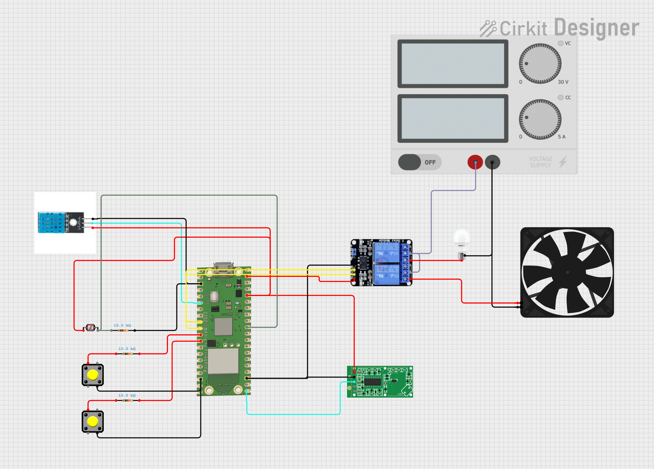
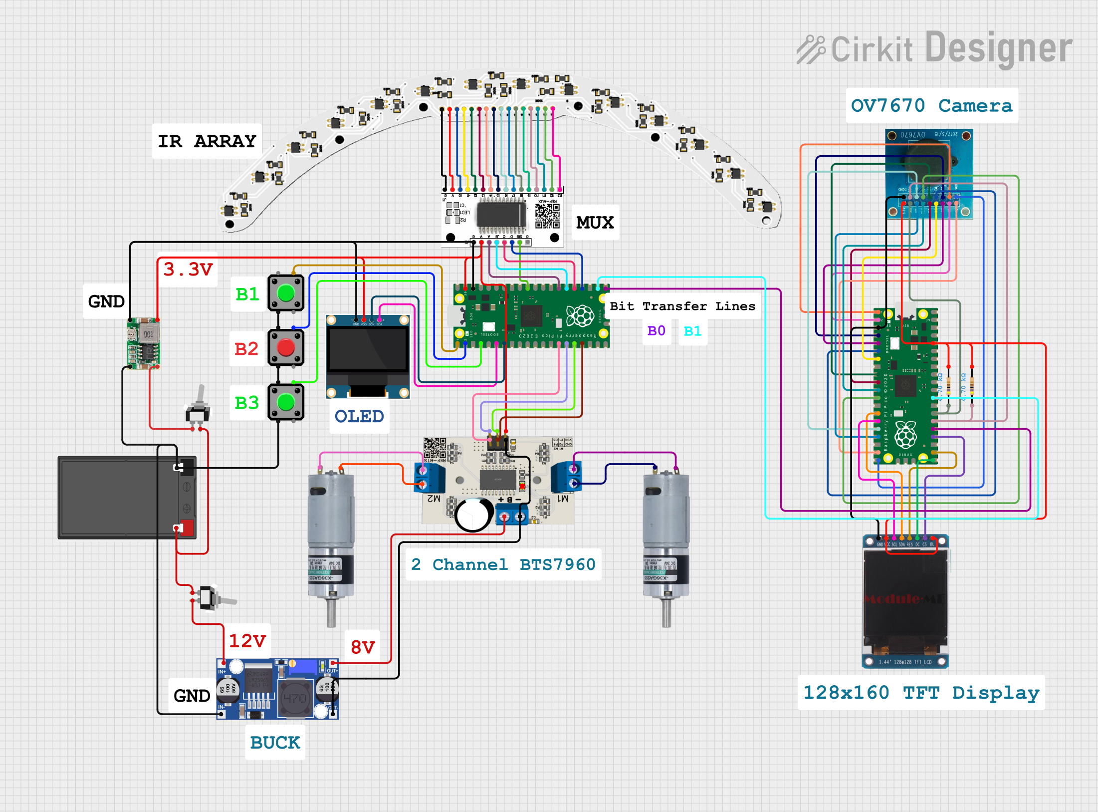
Explore Projects Built with raspberry pi pico
Technical Specifications
Key Technical Details
- Microcontroller: Raspberry Pi RP2040
- Processor: Dual-core ARM Cortex-M0+ @ 133 MHz
- Memory: 264KB SRAM, 2MB onboard QSPI flash
- GPIO Pins: 26 multi-function GPIO pins (3.3V logic level)
- Interfaces: I2C, SPI, UART, PWM, ADC (3 channels), USB 1.1
- Power Supply: 1.8V to 5.5V (via micro-USB or VSYS pin)
- Operating Temperature: -20°C to +85°C
- Dimensions: 51mm x 21mm
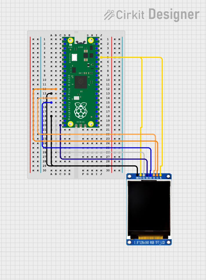
Pin Configuration and Descriptions
The Raspberry Pi Pico has 40 pins, including power, ground, and GPIO pins. Below is a summary of the pin configuration:
| Pin Number | Pin Name | Description |
|---|---|---|
| 1 | GP0 | GPIO0, UART0 TX, I2C0 SDA, SPI0 RX |
| 2 | GP1 | GPIO1, UART0 RX, I2C0 SCL, SPI0 CSn |
| 3 | GND | Ground |
| 4 | GP2 | GPIO2, UART1 TX, I2C1 SDA, SPI0 SCK |
| 5 | GP3 | GPIO3, UART1 RX, I2C1 SCL, SPI0 TX |
| 36 | 3V3(OUT) | 3.3V Output |
| 39 | VSYS | Power input (1.8V to 5.5V) |
| 40 | GND | Ground |
For a complete pinout diagram, refer to the official Raspberry Pi Pico documentation.
Usage Instructions
How to Use the Raspberry Pi Pico in a Circuit
Powering the Pico:
- Connect the Pico to a computer or power source via the micro-USB port.
- Alternatively, supply power through the VSYS pin (1.8V to 5.5V).
Programming the Pico:
- Install MicroPython or C/C++ development tools.
- For MicroPython, download the firmware from the Raspberry Pi website and flash it to the Pico.
- Use a code editor like Thonny (for MicroPython) or Visual Studio Code (for C/C++).
Connecting Peripherals:
- Use the GPIO pins to interface with sensors, actuators, or other devices.
- Ensure that all connected devices operate at 3.3V logic levels to avoid damage.
Example Circuit:
- Connect an LED to GPIO15 with a 330-ohm resistor in series.
- Use the following MicroPython code to blink the LED.
Example MicroPython Code
Import the machine and time modules
import machine import time
Configure GPIO15 as an output pin
led = machine.Pin(15, machine.Pin.OUT)
Blink the LED in a loop
while True: led.value(1) # Turn the LED on time.sleep(1) # Wait for 1 second led.value(0) # Turn the LED off time.sleep(1) # Wait for 1 second
Important Considerations and Best Practices
- Always check the voltage and current ratings of connected devices to avoid damage.
- Use level shifters if interfacing with 5V logic devices.
- Avoid shorting GPIO pins or connecting them directly to power or ground.
- Use decoupling capacitors for stable power supply in noisy environments.
Troubleshooting and FAQs
Common Issues and Solutions
The Pico is not detected by the computer:
- Ensure the micro-USB cable supports data transfer (not just charging).
- Hold the BOOTSEL button while connecting the Pico to the computer to enter USB mass storage mode.
MicroPython code is not running:
- Verify that the MicroPython firmware is correctly flashed.
- Check for syntax errors in the code.
Connected devices are not working:
- Confirm that the GPIO pins are configured correctly in the code.
- Check wiring and ensure proper voltage levels.
The Pico overheats or behaves erratically:
- Ensure the power supply voltage is within the specified range (1.8V to 5.5V).
- Avoid drawing excessive current from the GPIO pins.
FAQs
Q: Can I power the Pico with a battery?
A: Yes, you can power the Pico using a battery connected to the VSYS pin, as long as the voltage is between 1.8V and 5.5V.Q: How do I reset the Pico?
A: Press the RESET button (if available) or disconnect and reconnect the power supply.Q: Can I use the Pico with Arduino IDE?
A: Yes, the Pico is compatible with the Arduino IDE. Install the RP2040 board package to get started.Q: What is the maximum current the GPIO pins can source/sink?
A: Each GPIO pin can source/sink up to 12mA, with a total maximum current of 50mA for all GPIOs combined.