How to Use Osoyoo ESP32 38P Breakout Board: Examples, Pinouts, and Specs
Introduction
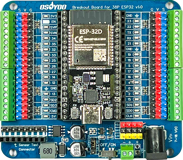
The Osoyoo ESP32 38P Breakout Board is a versatile development board built around the powerful ESP32 chip. It features 38 pins, offering easy access to GPIO, power, and communication interfaces. This board is ideal for Internet of Things (IoT) projects, prototyping, and applications requiring wireless connectivity, such as Wi-Fi and Bluetooth.
Explore Projects Built with Osoyoo ESP32 38P Breakout Board


Explore Projects Built with Osoyoo ESP32 38P Breakout Board
Common Applications and Use Cases
- IoT devices and smart home automation
- Wireless sensor networks
- Robotics and control systems
- Data logging and remote monitoring
- Prototyping and educational projects
Technical Specifications
The Osoyoo ESP32 38P Breakout Board is designed to provide robust performance and flexibility for a wide range of applications. Below are the key technical details:
Key Technical Details
- Microcontroller: ESP32 dual-core processor
- Clock Speed: Up to 240 MHz
- Flash Memory: 4 MB
- SRAM: 520 KB
- Wi-Fi: 802.11 b/g/n
- Bluetooth: BLE and Classic Bluetooth
- Operating Voltage: 3.3V
- Input Voltage (VIN): 5V (via USB or VIN pin)
- GPIO Pins: 30+ configurable pins
- Communication Interfaces: UART, SPI, I2C, PWM, ADC, DAC
- Analog Input Pins: 18 (12-bit ADC)
- Digital I/O Pins: 34
- PWM Channels: 16
- DAC Channels: 2 (8-bit resolution)
- Operating Temperature: -40°C to 85°C
Pin Configuration and Descriptions
The Osoyoo ESP32 38P Breakout Board features 38 pins, each with specific functions. Below is the pinout description:
| Pin Name | Function | Description |
|---|---|---|
| VIN | Power Input | Accepts 5V input to power the board. |
| GND | Ground | Common ground for the circuit. |
| 3V3 | Power Output | Provides 3.3V output for external components. |
| EN | Enable | Enables or disables the ESP32 chip. |
| IO0 | GPIO0 / Boot Mode | Used for boot mode selection or general-purpose I/O. |
| IO2 | GPIO2 | General-purpose I/O pin. |
| IO4 | GPIO4 | General-purpose I/O pin. |
| IO5 | GPIO5 | General-purpose I/O pin. |
| IO12 | GPIO12 | General-purpose I/O pin. |
| IO13 | GPIO13 | General-purpose I/O pin. |
| IO14 | GPIO14 | General-purpose I/O pin. |
| IO15 | GPIO15 | General-purpose I/O pin. |
| IO16 | GPIO16 | General-purpose I/O pin. |
| IO17 | GPIO17 | General-purpose I/O pin. |
| IO18 | GPIO18 / SPI_CLK | SPI clock pin or general-purpose I/O. |
| IO19 | GPIO19 / SPI_MISO | SPI MISO pin or general-purpose I/O. |
| IO21 | GPIO21 / I2C_SDA | I2C data pin or general-purpose I/O. |
| IO22 | GPIO22 / I2C_SCL | I2C clock pin or general-purpose I/O. |
| IO23 | GPIO23 / SPI_MOSI | SPI MOSI pin or general-purpose I/O. |
| IO25 | GPIO25 / DAC1 | DAC output or general-purpose I/O. |
| IO26 | GPIO26 / DAC2 | DAC output or general-purpose I/O. |
| IO27 | GPIO27 | General-purpose I/O pin. |
| IO32 | GPIO32 / ADC | Analog input or general-purpose I/O. |
| IO33 | GPIO33 / ADC | Analog input or general-purpose I/O. |
| IO34 | GPIO34 / ADC | Analog input (input-only pin). |
| IO35 | GPIO35 / ADC | Analog input (input-only pin). |
Usage Instructions
The Osoyoo ESP32 38P Breakout Board is easy to use and highly adaptable for various projects. Follow the steps below to get started:
How to Use the Component in a Circuit
Powering the Board:
- Connect the board to your computer via a USB cable for power and programming.
- Alternatively, supply 5V to the VIN pin and connect GND to the ground.
Programming the Board:
- Install the Arduino IDE and add the ESP32 board support package.
- Select "ESP32 Dev Module" from the Tools > Board menu.
- Connect the board to your computer and select the appropriate COM port.
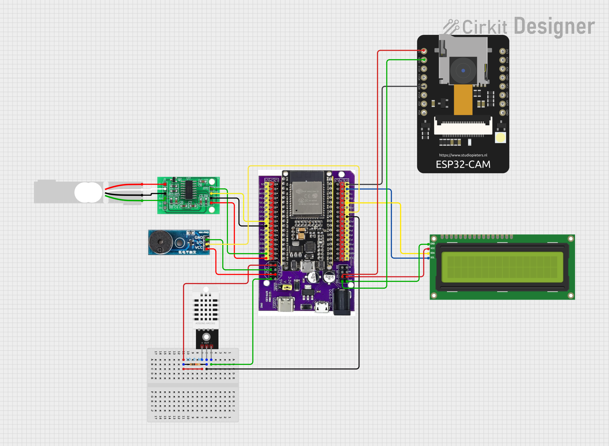
Connecting Peripherals:
- Use the GPIO pins to connect sensors, actuators, or other peripherals.
- For analog sensors, connect them to the ADC pins (e.g., IO32, IO33).
- For I2C devices, use IO21 (SDA) and IO22 (SCL).
- For SPI devices, use IO18 (CLK), IO19 (MISO), and IO23 (MOSI).
Uploading Code:
- Write your code in the Arduino IDE and click the upload button.
- Ensure the board is in programming mode by holding the BOOT button during upload if necessary.
Important Considerations and Best Practices
- Always use a level shifter when interfacing 5V devices with the ESP32's 3.3V GPIO pins.
- Avoid exceeding the maximum current rating of the GPIO pins (12 mA per pin).
- Use decoupling capacitors near power pins to reduce noise in sensitive circuits.
- Ensure proper grounding to avoid communication issues with peripherals.
Example Code for Arduino UNO Integration
Below is an example of how to blink an LED connected to GPIO2:
// Define the GPIO pin for the LED
const int ledPin = 2;

void setup() {
  // Set the LED pin as an output
  pinMode(ledPin, OUTPUT);
}

void loop() {
  // Turn the LED on
  digitalWrite(ledPin, HIGH);
  delay(1000); // Wait for 1 second

  // Turn the LED off
  digitalWrite(ledPin, LOW);
  delay(1000); // Wait for 1 second
}
Troubleshooting and FAQs
Common Issues Users Might Face
Board Not Detected by Computer:
- Ensure the USB cable is functional and supports data transfer.
- Verify that the correct COM port is selected in the Arduino IDE.
Code Upload Fails:
- Hold the BOOT button while uploading the code.
- Check that the correct board and port are selected in the Arduino IDE.
Wi-Fi Connection Issues:
- Verify the SSID and password in your code.
- Ensure the router is within range and supports 2.4 GHz Wi-Fi.
GPIO Pin Not Responding:
- Check for loose connections or incorrect wiring.
- Ensure the pin is not being used by another peripheral.
Solutions and Tips for Troubleshooting
- Use a multimeter to check power supply voltages and continuity in your circuit.
- Update the ESP32 board package in the Arduino IDE to the latest version.
- Refer to the ESP32 datasheet for detailed information on pin functions and limitations.
By following this documentation, you can effectively utilize the Osoyoo ESP32 38P Breakout Board for your projects.