How to Use TCA9548a: Examples, Pinouts, and Specs
Introduction
The TCA9548A is an I2C multiplexer that allows a single I2C master device to communicate with multiple I2C devices across up to eight independent I2C buses. This component is particularly useful in applications where multiple devices with the same I2C address need to coexist on the same system. By isolating each device on its own channel, the TCA9548A eliminates address conflicts and simplifies system design.
Explore Projects Built with TCA9548a


Explore Projects Built with TCA9548a
Common Applications and Use Cases
- Expanding the number of I2C devices in a system
- Managing I2C address conflicts
- Connecting multiple sensors, displays, or peripherals to a single microcontroller
- Applications in robotics, IoT, and data acquisition systems
Technical Specifications
Key Technical Details
- Operating Voltage (Vcc): 1.65V to 5.5V
- I2C Bus Voltage Range: 1.65V to 5.5V (supports level translation)
- Maximum Clock Frequency: 400 kHz (I2C Fast Mode)
- Number of Channels: 8
- I2C Address Range: 0x70 to 0x77 (configurable via A0, A1, A2 pins)
- Low Standby Current: 1 µA (typical)
- Package Type: TSSOP-16 or similar
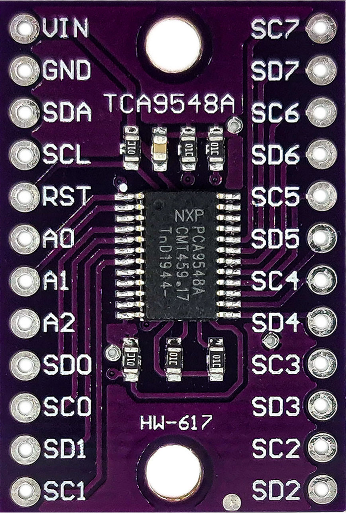
Pin Configuration and Descriptions
The TCA9548A has 16 pins, as described in the table below:
| Pin Number | Pin Name | Description |
|---|---|---|
| 1 | A0 | Address selection bit 0 (connect to Vcc or GND to set I2C address) |
| 2 | A1 | Address selection bit 1 (connect to Vcc or GND to set I2C address) |
| 3 | A2 | Address selection bit 2 (connect to Vcc or GND to set I2C address) |
| 4 | Vcc | Power supply input (1.65V to 5.5V) |
| 5 | SDA | I2C data line (connect to master SDA line) |
| 6 | SCL | I2C clock line (connect to master SCL line) |
| 7 | /RESET | Active-low reset input (pull low to reset the device) |
| 8 | GND | Ground connection |
| 9-16 | SD0-SD7 | I2C data lines for channels 0 to 7 (connect to slave devices' SDA lines) |
| Pin Number | Pin Name | Description |
|---|---|---|
| 9 | SC0 | I2C clock line for channel 0 (connect to slave device's SCL line) |
| 10 | SC1 | I2C clock line for channel 1 (connect to slave device's SCL line) |
| 11 | SC2 | I2C clock line for channel 2 (connect to slave device's SCL line) |
| 12 | SC3 | I2C clock line for channel 3 (connect to slave device's SCL line) |
| 13 | SC4 | I2C clock line for channel 4 (connect to slave device's SCL line) |
| 14 | SC5 | I2C clock line for channel 5 (connect to slave device's SCL line) |
| 15 | SC6 | I2C clock line for channel 6 (connect to slave device's SCL line) |
| 16 | SC7 | I2C clock line for channel 7 (connect to slave device's SCL line) |
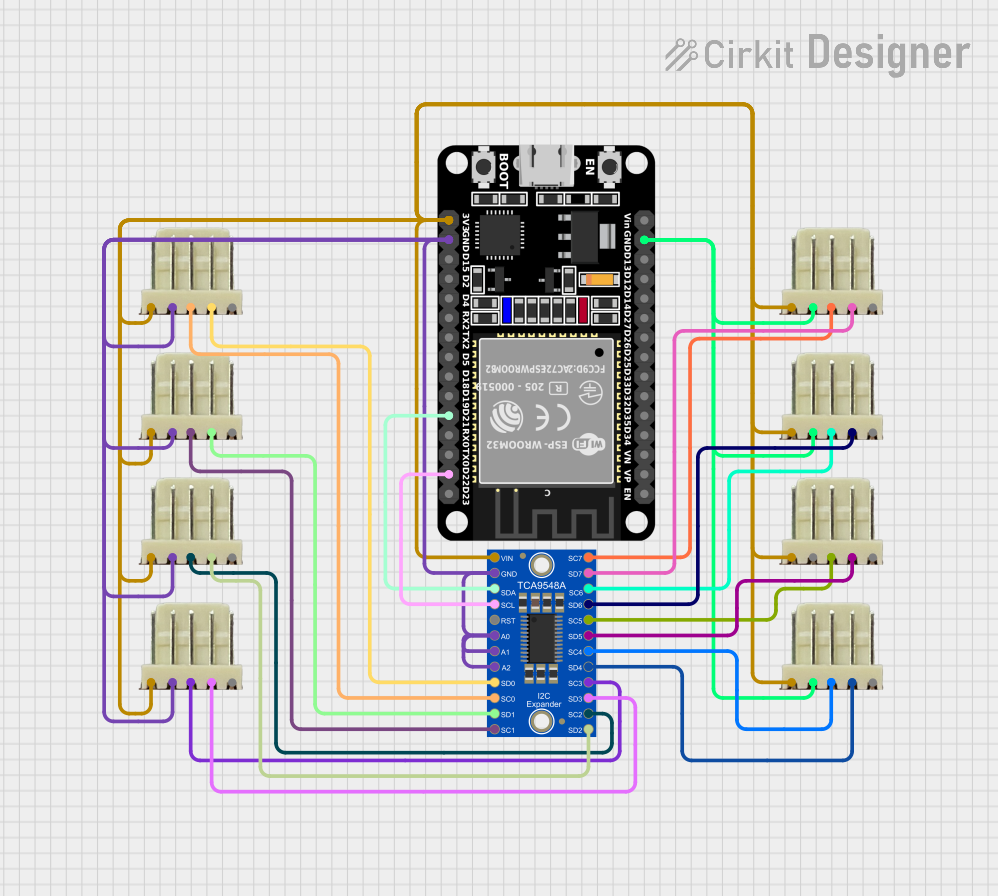
Usage Instructions
How to Use the TCA9548A in a Circuit
- Power Supply: Connect the Vcc pin to a power source (1.65V to 5.5V) and the GND pin to ground.
- I2C Address Configuration: Use the A0, A1, and A2 pins to set the I2C address of the TCA9548A. Connect these pins to either Vcc or GND to select an address in the range 0x70 to 0x77.
- I2C Master Connection: Connect the SDA and SCL pins of the TCA9548A to the corresponding SDA and SCL lines of the I2C master device.
- Channel Connections: Connect the SDA and SCL lines of each I2C slave device to the corresponding SDx and SCx pins of the TCA9548A.
- Reset Pin: Optionally, connect the /RESET pin to a microcontroller GPIO pin or a pull-up resistor to Vcc. Pull this pin low to reset the device.
Important Considerations and Best Practices
- Ensure that pull-up resistors are present on the SDA and SCL lines of the master I2C bus and each active channel.
- Avoid enabling multiple channels simultaneously unless the connected devices can tolerate shared bus communication.
- Use appropriate decoupling capacitors near the Vcc pin to stabilize the power supply.
Example Code for Arduino UNO
The following example demonstrates how to use the TCA9548A with an Arduino UNO to communicate with a device on channel 0.
#include <Wire.h>

// Define the TCA9548A I2C address (default is 0x70)
#define TCA9548A_ADDR 0x70

// Function to select a specific channel on the TCA9548A
void selectChannel(uint8_t channel) {
  if (channel > 7) return; // Ensure the channel is valid (0-7)
  Wire.beginTransmission(TCA9548A_ADDR);
  Wire.write(1 << channel); // Send the channel selection command
  Wire.endTransmission();
}

void setup() {
  Wire.begin(); // Initialize the I2C bus
  Serial.begin(9600); // Initialize serial communication for debugging

  // Select channel 0
  selectChannel(0);

  // Example: Communicate with a device on channel 0
  Wire.beginTransmission(0x40); // Replace 0x40 with the slave device's address
  Wire.write(0x00); // Example command to the slave device
  Wire.endTransmission();

  Serial.println("Communication with channel 0 initiated.");
}

void loop() {
  // Add your main code here
}
Troubleshooting and FAQs
Common Issues and Solutions
No Communication with Slave Devices:
- Verify that the TCA9548A is powered correctly and the GND pin is connected.
- Ensure the I2C address of the TCA9548A matches the address set in your code.
- Check that the correct channel is selected before communicating with a slave device.
I2C Bus Errors or Conflicts:
- Ensure that only one channel is active at a time.
- Verify that pull-up resistors are present on all active SDA and SCL lines.
Device Not Responding After Reset:
- Confirm that the /RESET pin is properly connected and not floating.
- Allow sufficient time for the TCA9548A to initialize after a reset.
FAQs
Q: Can I use the TCA9548A with 3.3V and 5V devices simultaneously?
A: Yes, the TCA9548A supports level translation, allowing devices with different voltage levels to coexist on separate channels.
Q: What happens if multiple channels are enabled at the same time?
A: Enabling multiple channels simultaneously can cause bus conflicts if the connected devices attempt to communicate at the same time. It is recommended to enable only one channel at a time.
Q: How do I determine the I2C address of the TCA9548A?
A: The I2C address is determined by the states of the A0, A1, and A2 pins. Refer to the datasheet for the address mapping.