
How to Use Rotary Potentiometer (Large): Examples, Pinouts, and Specs
 Design with Rotary Potentiometer (Large) in Cirkit Designer
Introduction
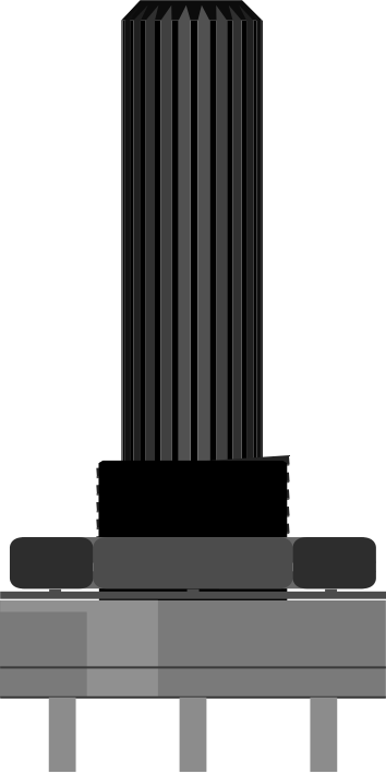
A rotary potentiometer is a variable resistor that allows for the adjustment of resistance by rotating a knob. The large size typically indicates a higher power rating or a more robust construction, making it suitable for applications requiring precise control of voltage or current.
Rotary potentiometers are widely used in electronic circuits for tasks such as adjusting volume in audio equipment, tuning circuits, or controlling brightness in lighting systems. Their simplicity and versatility make them a staple in both hobbyist and professional electronics projects.
Explore Projects Built with Rotary Potentiometer (Large)
 Open Project in Cirkit Designer
 Open Project in Cirkit Designer
 Open Project in Cirkit Designer
 Open Project in Cirkit Designer
Explore Projects Built with Rotary Potentiometer (Large)
Open Project in Cirkit DesignerOpen Project in Cirkit DesignerOpen Project in Cirkit DesignerOpen Project in Cirkit DesignerTechnical Specifications
Below are the key technical details for a typical large rotary potentiometer:
- Resistance Range: 1 kΩ to 1 MΩ (varies by model)
- Power Rating: 0.5 W to 2 W
- Tolerance: ±10% to ±20%
- Maximum Voltage: 250 V DC
- Rotation Angle: 270° (typical)
- Shaft Diameter: 6 mm (standard for large potentiometers)
- Mounting Type: Panel mount or PCB mount
- Operating Temperature: -40°C to +85°C
Pin Configuration and Descriptions
A rotary potentiometer typically has three pins. The table below describes their functions:
| Pin Number | Name | Description |
|---|---|---|
| 1 | Terminal 1 | One end of the resistive element. Connect to ground or a reference voltage. |
| 2 | Wiper | The adjustable middle pin. Outputs the variable resistance or voltage. |
| 3 | Terminal 2 | The other end of the resistive element. Connect to a voltage source. |
Usage Instructions
How to Use the Component in a Circuit
Basic Connection:
- Connect Terminal 1 to ground.
- Connect Terminal 2 to a voltage source (e.g., 5V).
- Connect the Wiper (Pin 2) to the input of the circuit where you need a variable voltage or resistance.
Adjusting Resistance:
- Rotate the knob to change the position of the wiper along the resistive element.
- This adjusts the resistance between the wiper and the two terminals, effectively dividing the voltage.
Example Application:
- Use the potentiometer as a voltage divider to provide a variable input to an analog pin of a microcontroller.
Important Considerations and Best Practices
- Power Rating: Ensure the potentiometer's power rating is not exceeded to avoid overheating or damage.
- Mechanical Stress: Avoid applying excessive force to the shaft to prevent mechanical failure.
- Debouncing: When used in digital circuits, consider software or hardware debouncing to handle noise caused by mechanical movement.
- Mounting: Secure the potentiometer properly to prevent movement during operation, especially in panel-mounted applications.
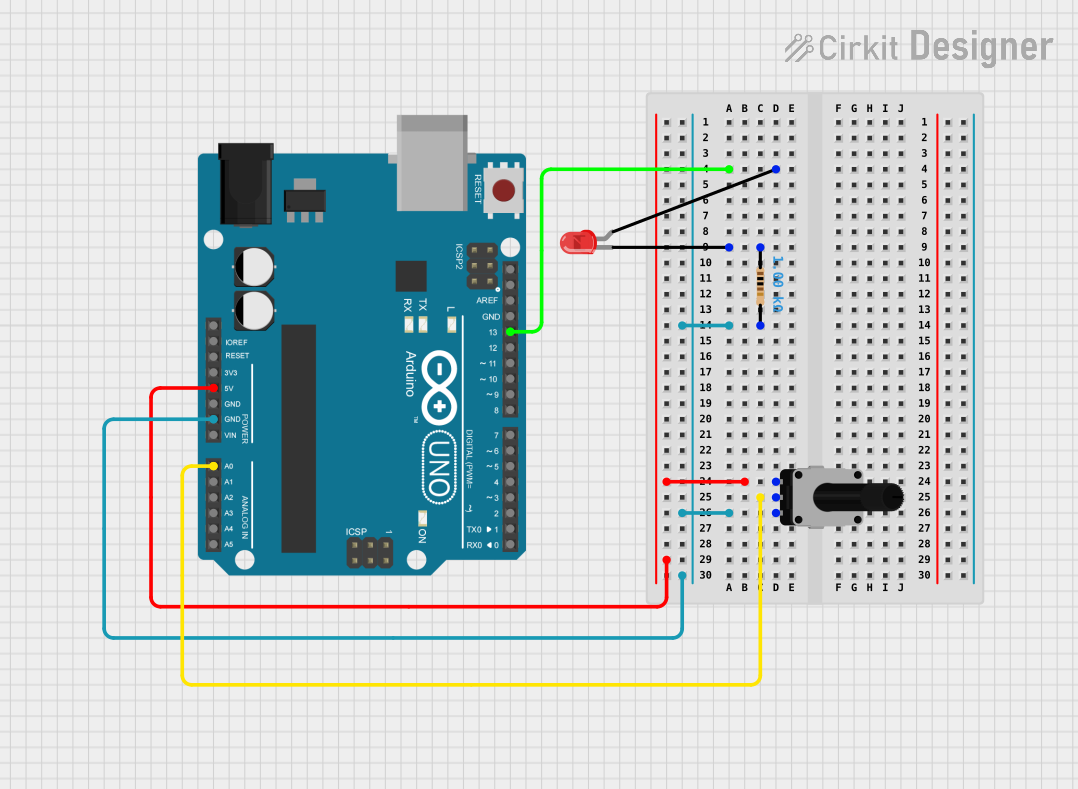
Example: Connecting to an Arduino UNO
Below is an example of how to use a rotary potentiometer with an Arduino UNO to read analog values:
// Define the analog pin connected to the potentiometer's wiper
const int potPin = A0;

void setup() {
  // Initialize serial communication for debugging
  Serial.begin(9600);
}

void loop() {
  // Read the analog value from the potentiometer (0-1023)
  int potValue = analogRead(potPin);

  // Print the value to the Serial Monitor
  Serial.print("Potentiometer Value: ");
  Serial.println(potValue);

  // Add a small delay to stabilize readings
  delay(100);
}
Explanation:
- Connect Terminal 1 to GND, Terminal 2 to 5V, and the Wiper to analog pin A0.
- The code reads the analog value from the potentiometer and prints it to the Serial Monitor.
Troubleshooting and FAQs
Common Issues
No Output or Incorrect Readings:
- Cause: Loose or incorrect connections.
- Solution: Double-check all connections, ensuring the wiper is connected to the correct input.
Potentiometer Feels Stiff or Doesn't Rotate Smoothly:
- Cause: Mechanical wear or debris inside the potentiometer.
- Solution: Replace the potentiometer or clean it carefully if possible.
Overheating:
- Cause: Exceeding the power rating.
- Solution: Use a potentiometer with a higher power rating or reduce the current through the component.
Inconsistent Output:
- Cause: Noise or poor contact between the wiper and resistive element.
- Solution: Use a high-quality potentiometer and consider adding a capacitor to filter noise.
FAQs
Q1: Can I use a rotary potentiometer to control a motor?
A1: Yes, but only indirectly. Use the potentiometer to control a signal (e.g., voltage) that drives a motor controller or PWM circuit. Do not connect the motor directly to the potentiometer.
Q2: How do I choose the right resistance value for my application?
A2: Consider the voltage range and current requirements of your circuit. For voltage dividers, ensure the total resistance is high enough to minimize current draw but low enough to avoid noise.
Q3: Can I use a rotary potentiometer as a rheostat?
A3: Yes, by connecting only two pins (one terminal and the wiper), you can use the potentiometer as a variable resistor (rheostat).
Q4: What is the lifespan of a rotary potentiometer?
A4: Lifespan depends on the quality and usage but typically ranges from 10,000 to 1,000,000 rotations.