How to Use IMU ICM-42688: Examples, Pinouts, and Specs
Introduction
The ICM-42688 is a 6-axis Inertial Measurement Unit (IMU) that integrates a 3-axis gyroscope and a 3-axis accelerometer into a single compact package. This high-performance sensor is designed for precise motion tracking and orientation sensing, making it ideal for applications such as robotics, drones, augmented reality (AR), virtual reality (VR), and mobile devices. With its low power consumption, high sensitivity, and advanced digital filtering capabilities, the ICM-42688 is well-suited for both battery-powered and high-precision systems.
Explore Projects Built with IMU ICM-42688


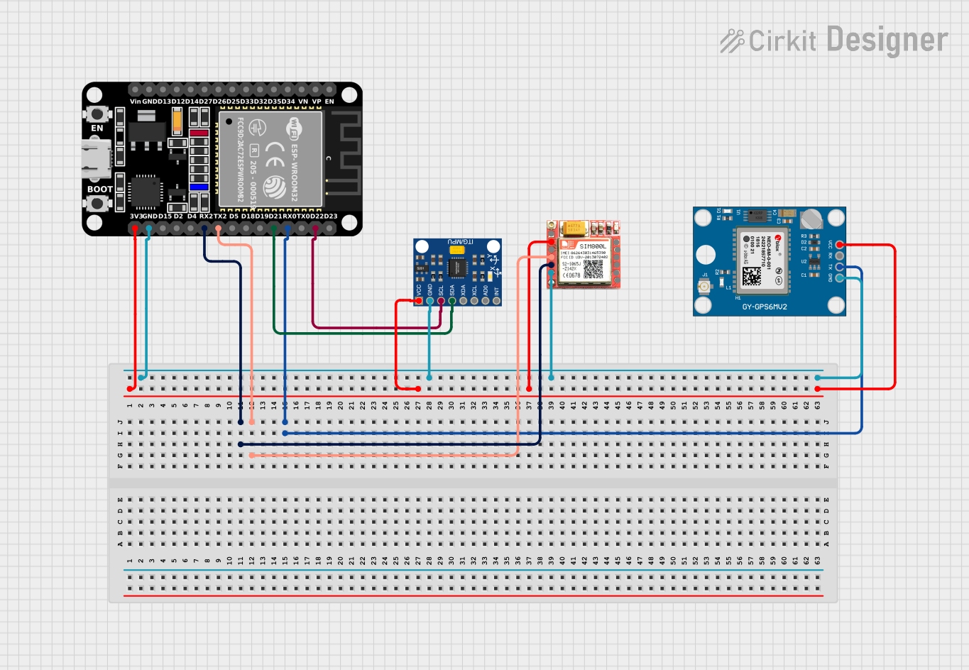
Explore Projects Built with IMU ICM-42688
Common Applications
- Robotics for motion control and navigation
- Drones for stabilization and flight control
- Mobile devices for gesture recognition and orientation sensing
- Wearable devices for fitness tracking and motion analysis
- AR/VR systems for immersive motion tracking
Technical Specifications
Key Technical Details
| Parameter | Value |
|---|---|
| Gyroscope Range | ±125, ±250, ±500, ±1000, ±2000 dps |
| Accelerometer Range | ±2g, ±4g, ±8g, ±16g |
| Gyroscope Sensitivity | 16.4 LSB/dps (at ±2000 dps) |
| Accelerometer Sensitivity | 16384 LSB/g (at ±2g) |
| Operating Voltage | 1.71V to 3.6V |
| Communication Interface | I²C (up to 1 MHz) / SPI (up to 7 MHz) |
| Power Consumption | 0.65 mA (low-power mode) |
| Operating Temperature | -40°C to +85°C |
| Package Size | 2.5 mm x 3 mm x 0.91 mm |
Pin Configuration and Descriptions
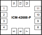
The ICM-42688 comes in a 14-pin LGA package. Below is the pin configuration:
| Pin Number | Pin Name | Description |
|---|---|---|
| 1 | VDD | Power supply input (1.71V to 3.6V) |
| 2 | VDDIO | I/O voltage supply |
| 3 | GND | Ground |
| 4 | SCL/SCLK | I²C clock / SPI clock input |
| 5 | SDA/SDI | I²C data / SPI data input |
| 6 | SDI/SDO | SPI data output (optional) |
| 7 | CS | Chip select for SPI (active low) |
| 8 | INT1 | Interrupt 1 output |
| 9 | INT2 | Interrupt 2 output |
| 10 | FSYNC | Frame synchronization input |
| 11 | RESV | Reserved (leave unconnected) |
| 12 | RESV | Reserved (leave unconnected) |
| 13 | RESV | Reserved (leave unconnected) |
| 14 | GND | Ground |
Usage Instructions
How to Use the ICM-42688 in a Circuit
- Power Supply: Connect the VDD pin to a regulated power source (1.71V to 3.6V) and the GND pins to the ground of your circuit. Ensure that the VDDIO pin is connected to the appropriate I/O voltage level.
- Communication Interface: Choose between I²C or SPI for communication:
- For I²C, connect the SCL and SDA pins to the corresponding I²C lines on your microcontroller. Use pull-up resistors (typically 4.7 kΩ) on both lines.
- For SPI, connect SCLK, SDI, SDO, and CS to the corresponding SPI lines on your microcontroller.
- Interrupts: Use the INT1 and INT2 pins to receive interrupt signals for motion events or data-ready notifications.
- Initialization: Configure the sensor by writing to its internal registers. Set the desired gyroscope and accelerometer ranges, output data rates, and filtering options.
Important Considerations and Best Practices
- Bypass Mode: If unused, leave the FSYNC and reserved pins unconnected.
- Decoupling Capacitors: Place a 0.1 µF ceramic capacitor close to the VDD pin to reduce noise.
- PCB Layout: Minimize trace lengths for the communication lines to reduce signal degradation.
- Orientation: Mount the sensor with the correct orientation as per your application to ensure accurate measurements.
Example Code for Arduino UNO
Below is an example of how to interface the ICM-42688 with an Arduino UNO using the I²C protocol:
#include <Wire.h>

// ICM-42688 I2C address (default)
#define ICM42688_ADDR 0x68

// Register addresses
#define WHO_AM_I 0x75
#define PWR_MGMT_1 0x06
#define ACCEL_XOUT_H 0x2D

void setup() {
  Wire.begin(); // Initialize I2C communication
  Serial.begin(9600); // Initialize serial communication for debugging

  // Wake up the ICM-42688
  Wire.beginTransmission(ICM42688_ADDR);
  Wire.write(PWR_MGMT_1); // Power management register
  Wire.write(0x01); // Set to normal mode
  Wire.endTransmission();

  // Verify communication by reading the WHO_AM_I register
  Wire.beginTransmission(ICM42688_ADDR);
  Wire.write(WHO_AM_I);
  Wire.endTransmission();
  Wire.requestFrom(ICM42688_ADDR, 1);

  if (Wire.available()) {
    byte whoAmI = Wire.read();
    Serial.print("WHO_AM_I: 0x");
    Serial.println(whoAmI, HEX);
  } else {
    Serial.println("Failed to communicate with ICM-42688");
  }
}

void loop() {
  // Read accelerometer X-axis high byte
  Wire.beginTransmission(ICM42688_ADDR);
  Wire.write(ACCEL_XOUT_H);
  Wire.endTransmission();
  Wire.requestFrom(ICM42688_ADDR, 1);

  if (Wire.available()) {
    byte accelXHigh = Wire.read();
    Serial.print("Accel X High Byte: ");
    Serial.println(accelXHigh);
  }

  delay(500); // Delay for readability
}
Troubleshooting and FAQs
Common Issues
No Communication with the Sensor:
- Ensure the correct I²C address (default: 0x68) is being used.
- Verify pull-up resistors are connected to the I²C lines.
- Check the power supply voltage and connections.
Incorrect or No Data Output:
- Confirm that the sensor is properly initialized by writing to the PWR_MGMT_1 register.
- Verify that the gyroscope and accelerometer ranges are configured correctly.
High Noise in Measurements:
- Use appropriate digital filtering settings to reduce noise.
- Ensure the sensor is mounted securely to avoid mechanical vibrations.
Solutions and Tips
- Debugging Communication: Use a logic analyzer to monitor I²C or SPI signals.
- Power Stability: Use a low-noise power supply and decoupling capacitors to ensure stable operation.
- Firmware Updates: Check for firmware updates or libraries that support the ICM-42688 for your platform.
By following this documentation, you can effectively integrate the ICM-42688 into your projects and achieve accurate motion sensing and orientation tracking.