
How to Use 11LC160: Examples, Pinouts, and Specs
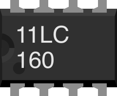
 Design with 11LC160 in Cirkit Designer
Introduction
The 11LC160 is a 16-bit static random-access memory (SRAM) chip, designed for high-speed data storage and retrieval in electronic circuits. It features low power consumption, making it ideal for battery-powered devices. The 11LC160 is commonly used in applications requiring fast access times, such as data logging, buffering, and temporary data storage in embedded systems.
Explore Projects Built with 11LC160
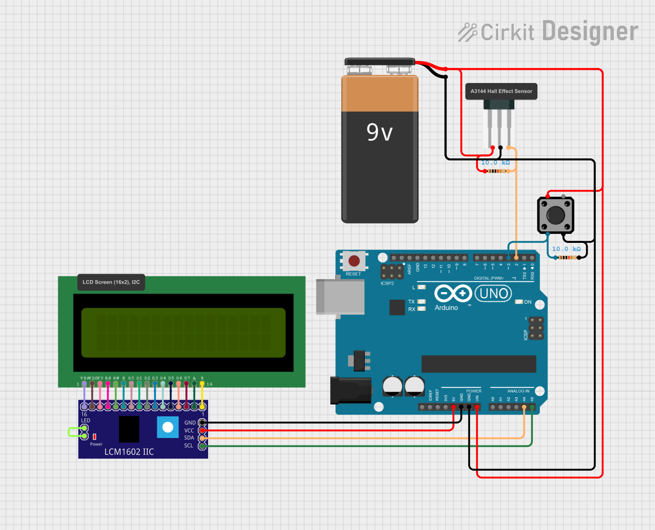 Open Project in Cirkit Designer
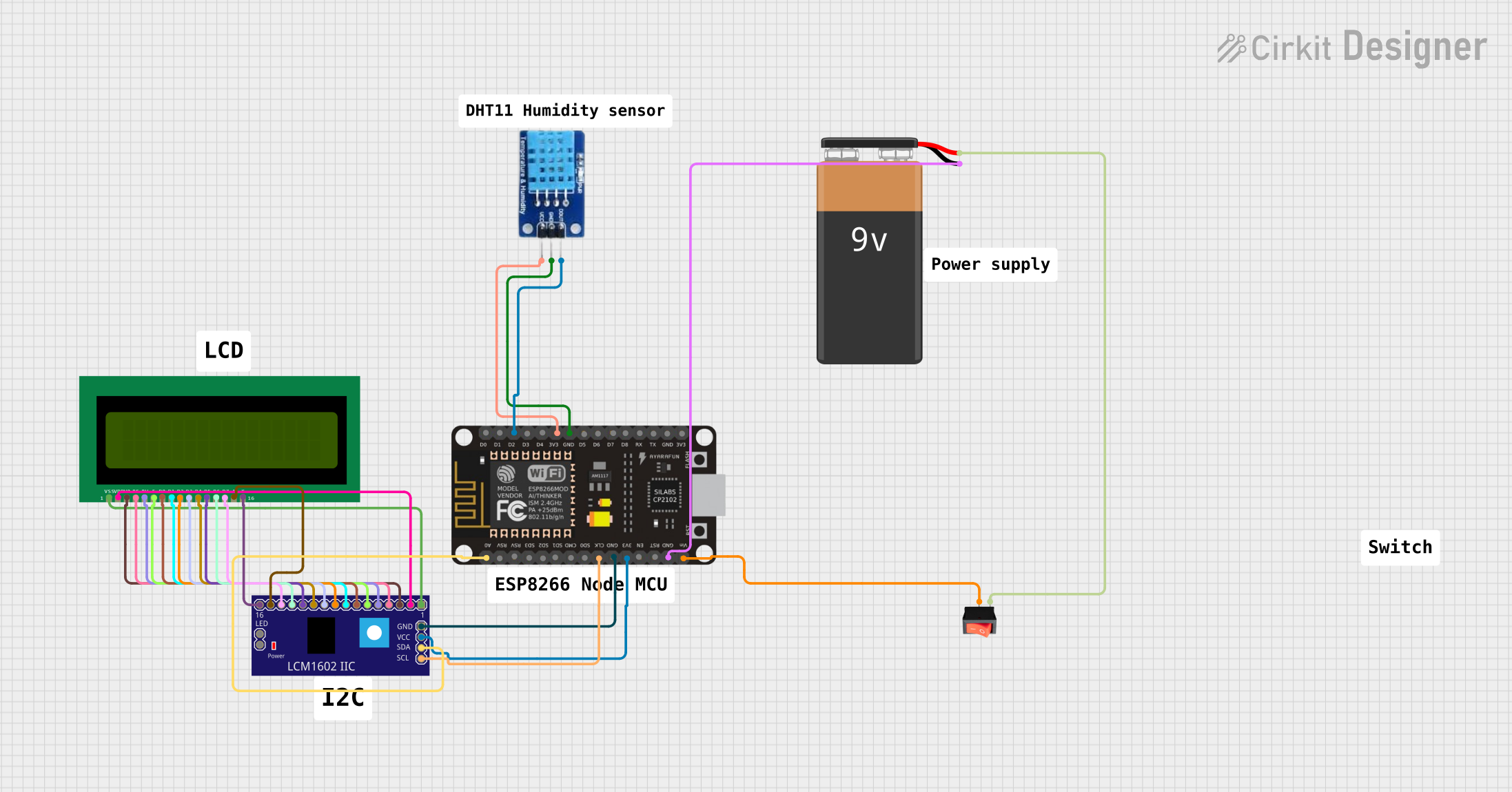 Open Project in Cirkit Designer
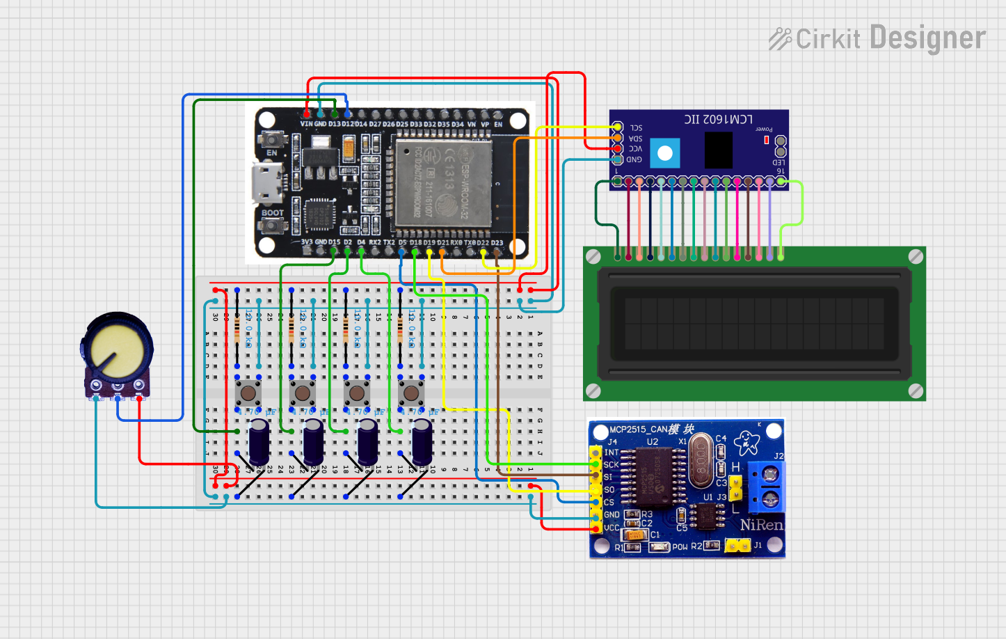 Open Project in Cirkit Designer
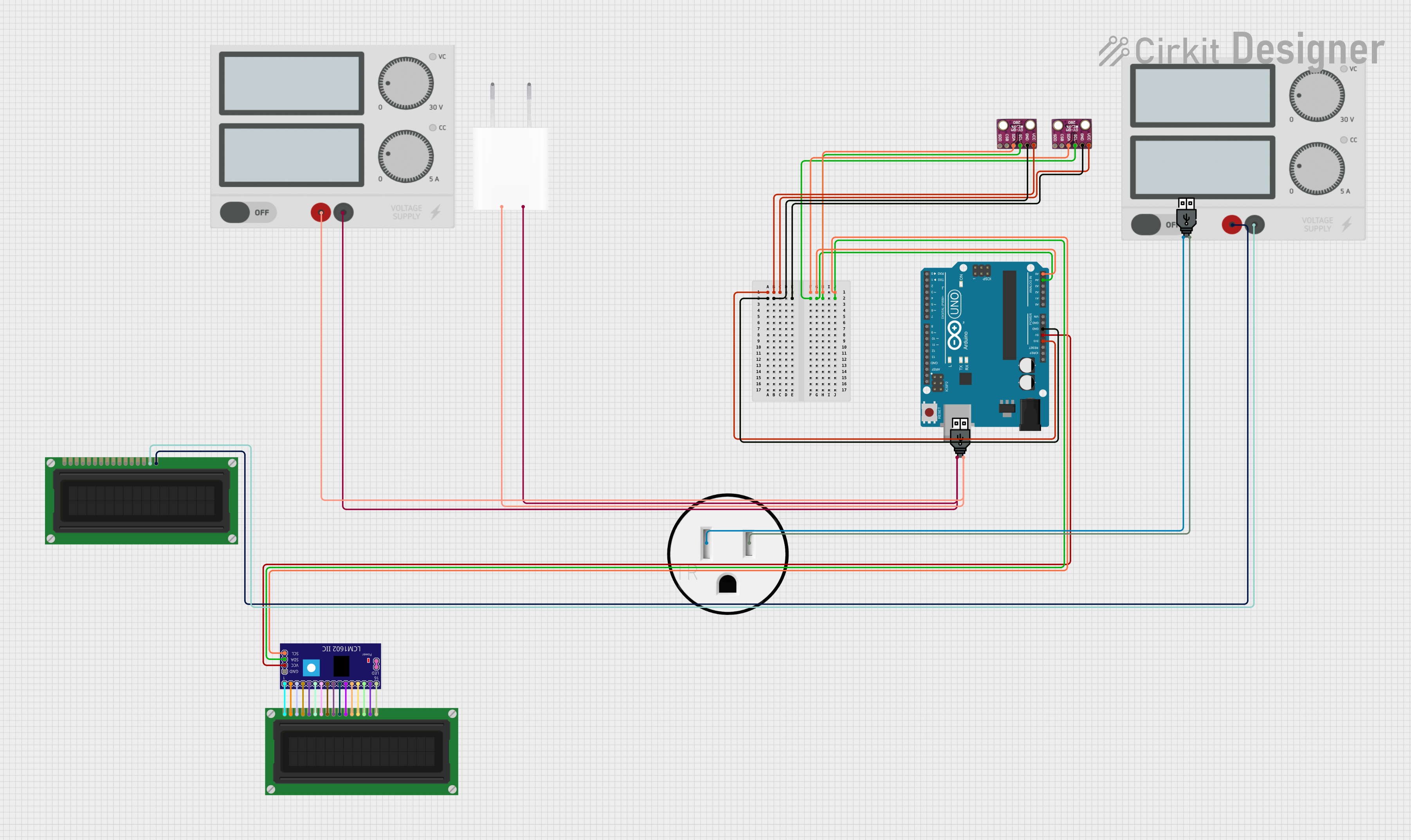 Open Project in Cirkit Designer
Explore Projects Built with 11LC160
Open Project in Cirkit DesignerOpen Project in Cirkit DesignerOpen Project in Cirkit DesignerOpen Project in Cirkit DesignerCommon Applications:
- Data logging in IoT devices
- Temporary data storage in microcontroller-based systems
- High-speed buffering in communication systems
- Memory expansion for low-power embedded devices
Technical Specifications
Key Technical Details:
| Parameter | Value |
|---|---|
| Memory Size | 16 Kbits (2 KB) |
| Memory Type | Static RAM (SRAM) |
| Interface | Serial Peripheral Interface (SPI) |
| Operating Voltage Range | 1.8V to 5.5V |
| Standby Current | 1 µA (typical) |
| Operating Current | 1 mA (typical) at 1 MHz |
| Maximum Clock Frequency | 10 MHz |
| Temperature Range | -40°C to +85°C |
| Package Types | 8-pin PDIP, SOIC, TSSOP |
Pin Configuration and Descriptions:
The 11LC160 is available in an 8-pin package. Below is the pinout and description:
| Pin Number | Pin Name | Description |
|---|---|---|
| 1 | CS | Chip Select: Enables communication with the chip |
| 2 | SO | Serial Data Output: Outputs data to the master |
| 3 | WP | Write Protect: Disables write operations when active |
| 4 | VSS | Ground: Connect to system ground |
| 5 | SI | Serial Data Input: Receives data from the master |
| 6 | SCK | Serial Clock: Clock signal for SPI communication |
| 7 | HOLD | Hold: Pauses communication without resetting the chip |
| 8 | VCC | Power Supply: Connect to a voltage source (1.8V-5.5V) |
Usage Instructions
How to Use the 11LC160 in a Circuit:
- Power Supply: Connect the VCC pin to a stable voltage source (1.8V to 5.5V) and the VSS pin to ground.
- SPI Communication: Interface the 11LC160 with a microcontroller or processor using the SPI protocol. Connect the
CS,SCK,SI, andSOpins to the corresponding SPI pins on the microcontroller. - Write Protection: If write protection is required, connect the
WPpin to VCC. Otherwise, connect it to ground. - Hold Function: If the hold function is not used, connect the
HOLDpin to VCC.
Important Considerations:
- Ensure the SPI clock frequency does not exceed 10 MHz.
- Use decoupling capacitors (e.g., 0.1 µF) near the VCC pin to stabilize the power supply.
- Avoid leaving unused pins floating; connect them to VCC or ground as specified.
Example: Connecting the 11LC160 to an Arduino UNO
Below is an example of how to connect and use the 11LC160 with an Arduino UNO:
Circuit Connections:
| 11LC160 Pin | Arduino UNO Pin |
|---|---|
| CS | Pin 10 |
| SO | Pin 12 (MISO) |
| SI | Pin 11 (MOSI) |
| SCK | Pin 13 (SCK) |
| VCC | 5V |
| VSS | GND |
| WP | GND |
| HOLD | 5V |
Arduino Code Example:
#include <SPI.h>

// Define 11LC160 pin connections
const int CS_PIN = 10;

void setup() {
  // Initialize SPI communication
  SPI.begin();

  // Set the Chip Select pin as output
  pinMode(CS_PIN, OUTPUT);

  // Deselect the chip by setting CS high
  digitalWrite(CS_PIN, HIGH);

  Serial.begin(9600);
  Serial.println("11LC160 SRAM Initialized");
}

void loop() {
  // Example: Write and read a byte from the 11LC160

  // Write operation
  digitalWrite(CS_PIN, LOW); // Select the chip
  SPI.transfer(0x02);        // Write instruction
  SPI.transfer(0x00);        // Address high byte
  SPI.transfer(0x01);        // Address low byte
  SPI.transfer(0x55);        // Data to write (0x55)
  digitalWrite(CS_PIN, HIGH); // Deselect the chip

  delay(10); // Wait for the write to complete

  // Read operation
  digitalWrite(CS_PIN, LOW); // Select the chip
  SPI.transfer(0x03);        // Read instruction
  SPI.transfer(0x00);        // Address high byte
  SPI.transfer(0x01);        // Address low byte
  byte data = SPI.transfer(0x00); // Read data
  digitalWrite(CS_PIN, HIGH); // Deselect the chip

  // Print the read data
  Serial.print("Read Data: 0x");
  Serial.println(data, HEX);

  delay(1000); // Wait before the next operation
}
Notes:
- The above code demonstrates basic write and read operations. Modify the address and data as needed for your application.
- Ensure proper SPI settings (e.g., clock polarity and phase) if using a different microcontroller.
Troubleshooting and FAQs
Common Issues:
No Data Read from the Chip:
- Verify the SPI connections and ensure the
CSpin is correctly toggled. - Check the power supply voltage and ensure it is within the specified range.
- Verify the SPI connections and ensure the
Write Operations Not Working:
- Ensure the
WPpin is connected to ground to enable write operations. - Verify the SPI clock frequency does not exceed 10 MHz.
- Ensure the
Unstable Operation:
- Add a decoupling capacitor (0.1 µF) near the VCC pin to filter noise.
- Ensure proper grounding and minimize noise in the SPI lines.
FAQs:
Q: Can the 11LC160 be used with 3.3V systems?
A: Yes, the 11LC160 operates within a voltage range of 1.8V to 5.5V, making it compatible with 3.3V systems.
Q: What is the maximum data retention time?
A: The 11LC160 is a static RAM chip, so data is retained as long as power is supplied.
Q: Can I use multiple 11LC160 chips in the same circuit?
A: Yes, you can use multiple chips by connecting their CS pins to separate GPIO pins on the microcontroller.
Q: Is the 11LC160 compatible with I2C?
A: No, the 11LC160 uses the SPI protocol for communication.