How to Use MinIMU-9 v6: Examples, Pinouts, and Specs
Introduction
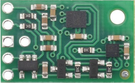
The MinIMU-9 v6 by Pololu (Part ID: IMU) is a compact and cost-effective inertial measurement unit (IMU) that integrates a 3-axis accelerometer, a 3-axis gyroscope, and a 3-axis magnetometer. This versatile sensor is designed to measure motion, orientation, and magnetic field data, making it ideal for applications such as robotics, drones, motion tracking, and navigation systems. Its small form factor and I²C/SPI communication interfaces make it easy to integrate into a wide range of projects.
Explore Projects Built with MinIMU-9 v6


Explore Projects Built with MinIMU-9 v6
Common Applications
- Robotics for orientation and motion sensing
- Drones for stabilization and navigation
- Motion tracking in wearable devices
- Navigation systems for heading and tilt compensation
- Gaming controllers and virtual reality systems
Technical Specifications
Key Technical Details
| Parameter | Specification |
|---|---|
| Accelerometer | ±2/±4/±8/±16 g selectable range |
| Gyroscope | ±125/±250/±500/±1000/±2000 dps selectable range |
| Magnetometer | ±4/±8/±12/±16 gauss selectable range |
| Communication Interfaces | I²C (default) and SPI |
| Operating Voltage | 2.5 V to 5.5 V |
| Current Consumption | ~10 mA (typical) |
| Dimensions | 20 mm × 13 mm × 3 mm |
| Weight | 0.6 g |
| Operating Temperature Range | -40°C to +85°C |
Pin Configuration and Descriptions
The MinIMU-9 v6 has a total of 8 pins. The table below describes each pin:
| Pin Name | Pin Number | Description |
|---|---|---|
| VIN | 1 | Power supply input (2.5 V to 5.5 V) |
| GND | 2 | Ground connection |
| SCL | 3 | I²C clock line (or SPI clock line in SPI mode) |
| SDA | 4 | I²C data line (or SPI data input in SPI mode) |
| SDO | 5 | I²C address selection (or SPI data output in SPI mode) |
| CS | 6 | Chip select for SPI mode (active low) |
| INT1 | 7 | Interrupt output 1 |
| INT2 | 8 | Interrupt output 2 |
Usage Instructions
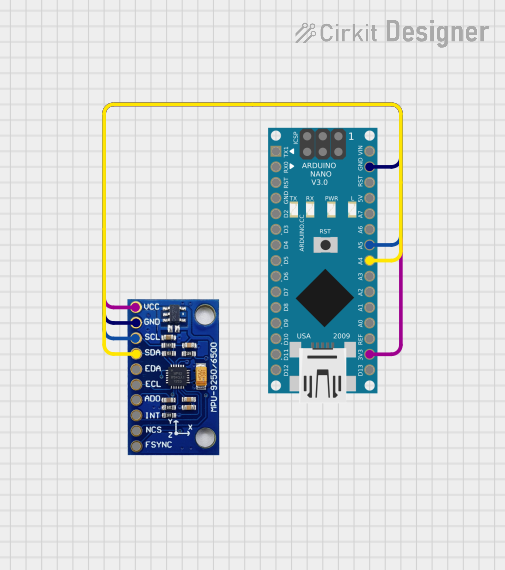
How to Use the MinIMU-9 v6 in a Circuit
- Power the Sensor: Connect the VIN pin to a 3.3 V or 5 V power source and the GND pin to ground.
- Choose Communication Mode:
- For I²C, connect the SCL and SDA pins to the corresponding I²C lines on your microcontroller.
- For SPI, connect the SCL, SDA, SDO, and CS pins to the appropriate SPI lines.
- Configure the Sensor: Use the I²C or SPI interface to configure the accelerometer, gyroscope, and magnetometer settings (e.g., range, data rate).
- Read Sensor Data: Continuously poll the sensor registers to retrieve raw accelerometer, gyroscope, and magnetometer data.
- Process Data: Apply sensor fusion algorithms (e.g., a complementary filter or Kalman filter) to combine the data and calculate orientation.
Important Considerations and Best Practices
- Pull-Up Resistors: If using I²C, ensure that pull-up resistors (typically 4.7 kΩ) are present on the SCL and SDA lines.
- Voltage Compatibility: The MinIMU-9 v6 is compatible with both 3.3 V and 5 V systems, but ensure your microcontroller's logic levels match.
- Magnetic Interference: Keep the sensor away from strong magnetic fields to avoid interference with the magnetometer.
- Mounting Orientation: Mount the sensor securely and in a fixed orientation to ensure accurate readings.
- Calibration: Perform calibration for the accelerometer, gyroscope, and magnetometer to improve accuracy.
Example Code for Arduino UNO
Below is an example of how to interface the MinIMU-9 v6 with an Arduino UNO using the I²C interface:
#include <Wire.h>

// I2C addresses for the accelerometer/gyroscope and magnetometer
#define LSM6DS33_ADDR  0x6B  // Accelerometer and gyroscope
#define LIS3MDL_ADDR   0x1E  // Magnetometer

void setup() {
  Wire.begin(); // Initialize I2C communication
  Serial.begin(9600); // Start serial communication for debugging

  // Initialize the accelerometer and gyroscope
  Wire.beginTransmission(LSM6DS33_ADDR);
  Wire.write(0x10); // CTRL1_XL register
  Wire.write(0x80); // Set accelerometer to 1.66 kHz, ±2 g
  Wire.endTransmission();

  Wire.beginTransmission(LSM6DS33_ADDR);
  Wire.write(0x11); // CTRL2_G register
  Wire.write(0x80); // Set gyroscope to 1.66 kHz, ±125 dps
  Wire.endTransmission();

  // Initialize the magnetometer
  Wire.beginTransmission(LIS3MDL_ADDR);
  Wire.write(0x20); // CTRL_REG1 register
  Wire.write(0x70); // Set magnetometer to 10 Hz, high-performance mode
  Wire.endTransmission();
}

void loop() {
  // Read accelerometer data
  Wire.beginTransmission(LSM6DS33_ADDR);
  Wire.write(0x28 | 0x80); // Start reading at OUTX_L_XL (auto-increment enabled)
  Wire.endTransmission();
  Wire.requestFrom(LSM6DS33_ADDR, 6); // Request 6 bytes (X, Y, Z)
  int16_t ax = Wire.read() | (Wire.read() << 8);
  int16_t ay = Wire.read() | (Wire.read() << 8);
  int16_t az = Wire.read() | (Wire.read() << 8);

  // Print accelerometer data
  Serial.print("Accel X: "); Serial.print(ax);
  Serial.print(" Y: "); Serial.print(ay);
  Serial.print(" Z: "); Serial.println(az);

  delay(100); // Delay for readability
}
Troubleshooting and FAQs
Common Issues and Solutions
No Data from the Sensor
- Solution: Verify the wiring, especially the SCL and SDA connections. Ensure pull-up resistors are present on the I²C lines.
- Tip: Check the I²C address of the sensor using an I²C scanner sketch.
Inaccurate Readings
- Solution: Perform a calibration for the accelerometer, gyroscope, and magnetometer. Ensure the sensor is mounted securely and away from magnetic interference.
- Tip: Use sensor fusion algorithms to improve accuracy.
Communication Errors
- Solution: Ensure the correct I²C or SPI settings are used. Check for loose connections or incorrect logic levels.
FAQs
Q: Can the MinIMU-9 v6 be used with a 3.3 V microcontroller?
- A: Yes, the sensor is compatible with both 3.3 V and 5 V systems.
Q: How do I select the I²C address?
- A: The I²C address can be changed by connecting the SDO pin to GND (default address) or VIN (alternate address).
Q: Do I need to use all three sensors (accelerometer, gyroscope, magnetometer)?
- A: No, you can use any combination of the sensors depending on your application.
This documentation provides a comprehensive guide to using the Pololu MinIMU-9 v6. For further details, refer to the official datasheet and user manual.