How to Use Roboclaw 2x7A Motor Controller: Examples, Pinouts, and Specs
Introduction
The Roboclaw 2x7A Motor Controller is a dual-channel motor driver designed to control two DC motors with a maximum continuous current of 7A per channel. It offers advanced features such as speed and direction control, encoder feedback, and support for multiple communication protocols, including UART, I2C, and RC Pulse. This versatile motor controller is ideal for robotics, automation systems, and other applications requiring precise motor control.
Explore Projects Built with Roboclaw 2x7A Motor Controller
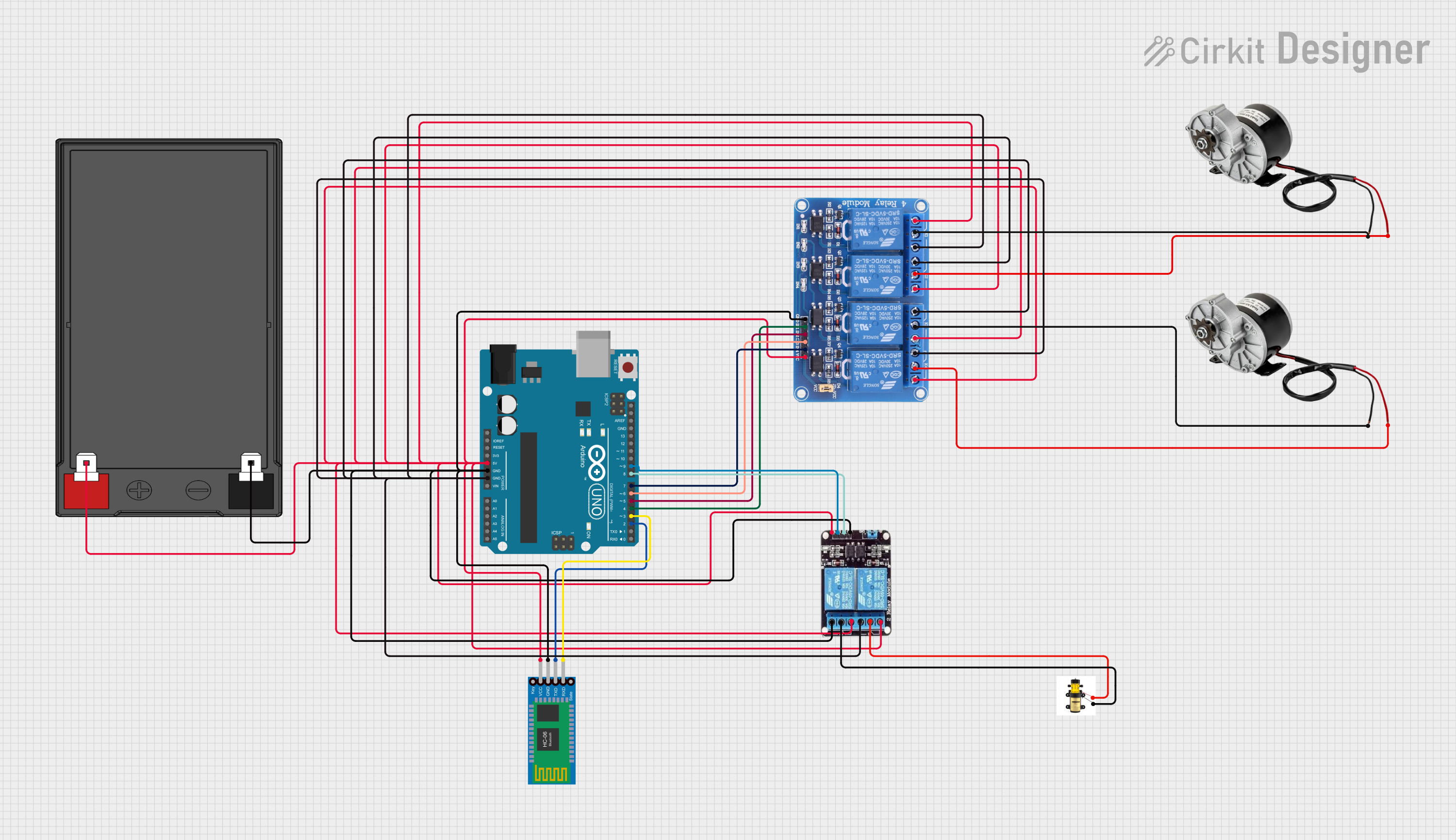

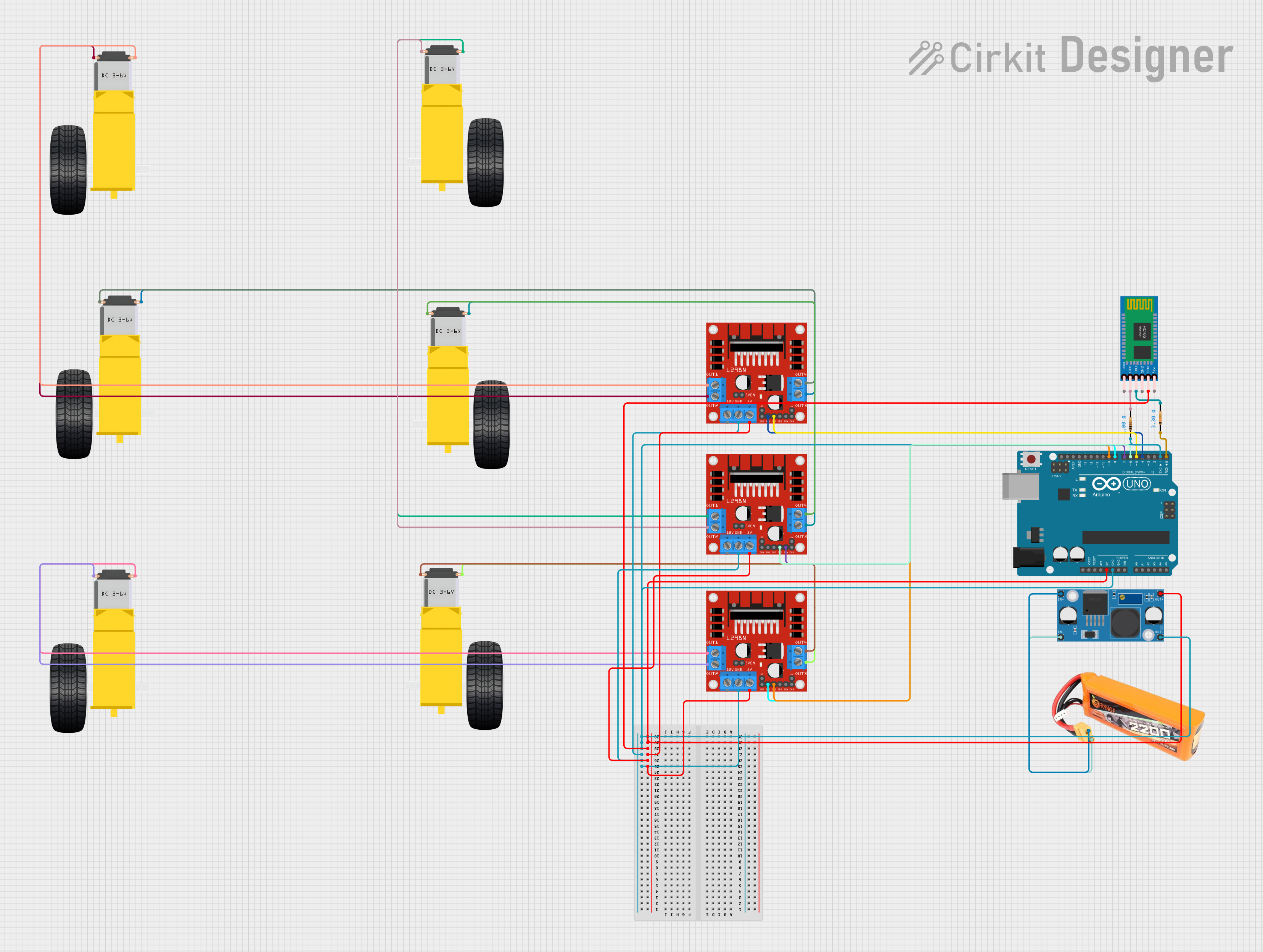
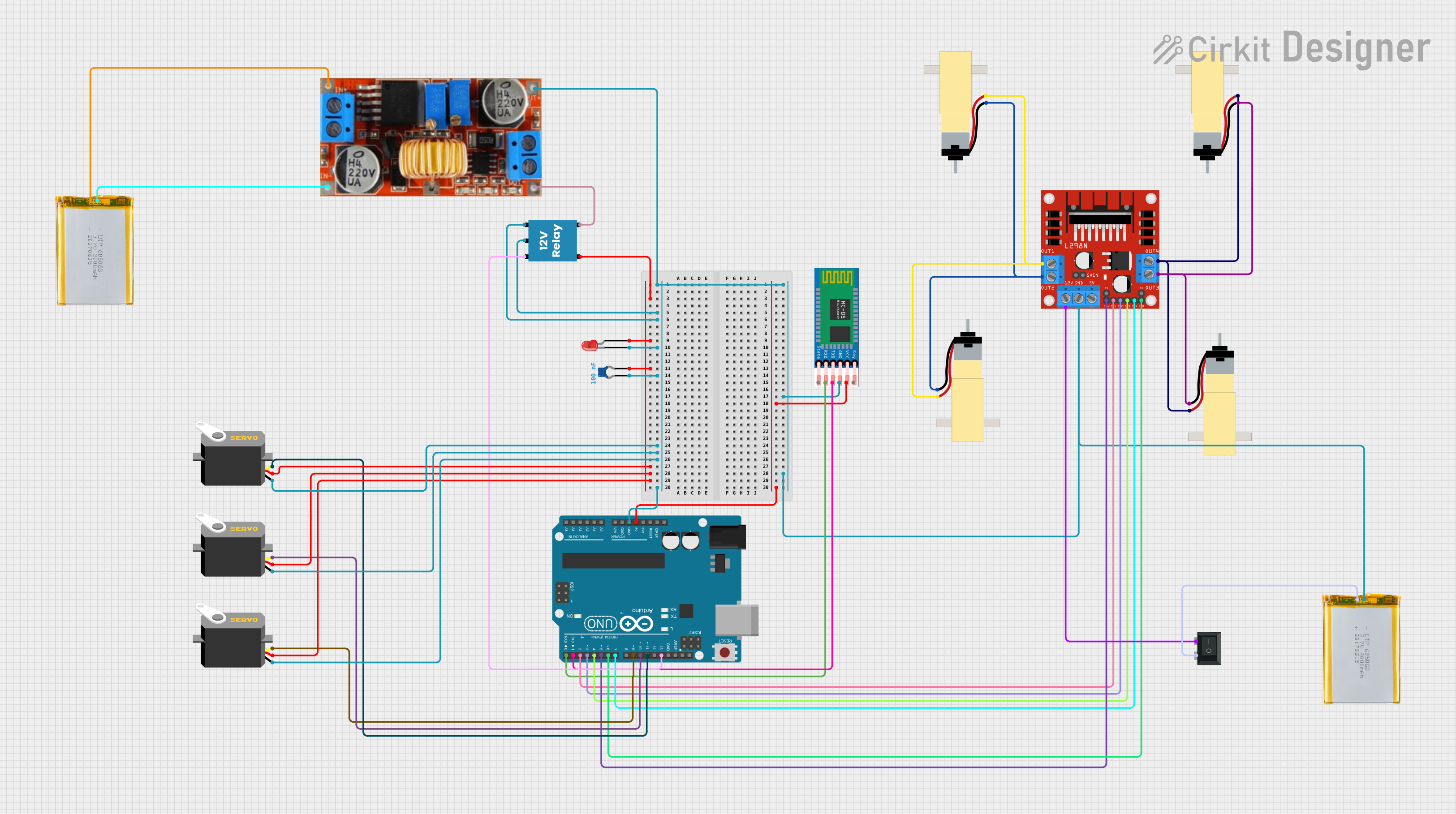
Explore Projects Built with Roboclaw 2x7A Motor Controller
Common Applications and Use Cases
- Robotics platforms for controlling drive motors
- Automated conveyor systems
- Remote-controlled vehicles
- Industrial automation requiring precise motor speed and position control
- Hobbyist projects involving DC motors
Technical Specifications
Key Technical Details
- Input Voltage Range: 6V to 30V DC
- Continuous Current: 7A per channel
- Peak Current: 15A per channel (for short durations)
- Communication Protocols: UART, I2C, RC Pulse, USB
- Control Modes: Speed, direction, and position control
- Encoder Support: Quadrature encoders for closed-loop control
- Dimensions: 2.25" x 2.0" x 0.5" (57mm x 51mm x 13mm)
- Weight: 1.5 oz (42.5g)
Pin Configuration and Descriptions
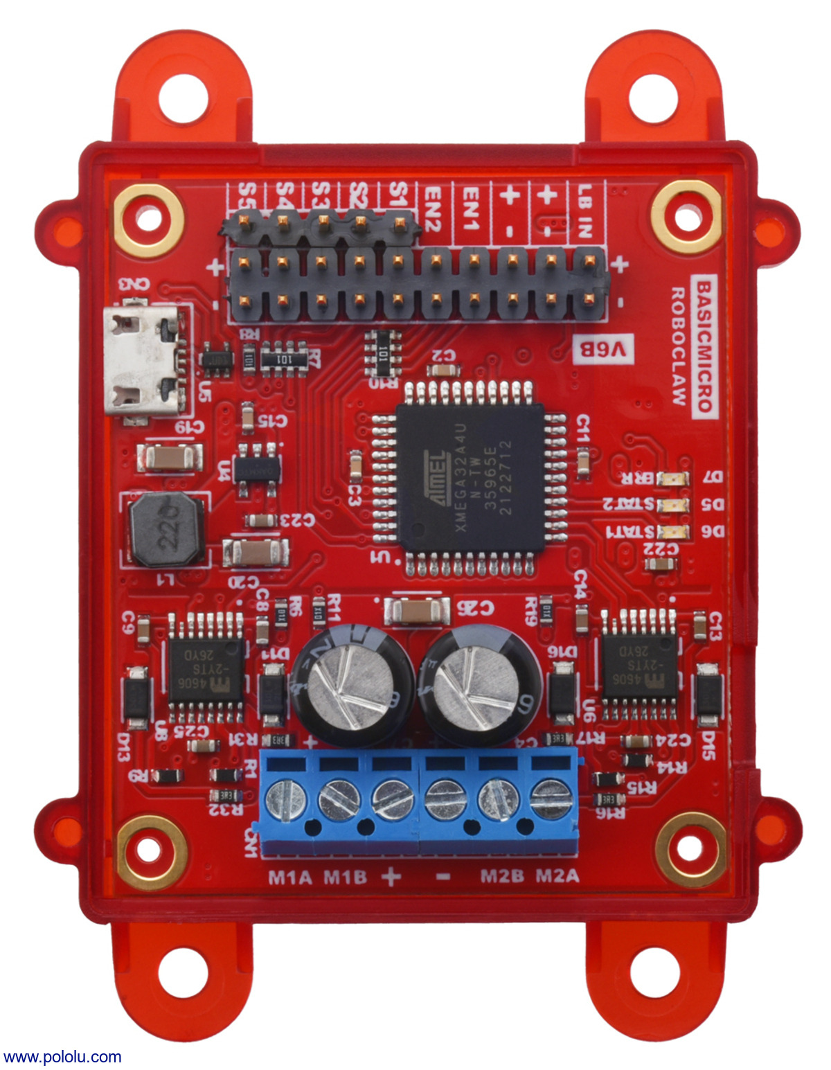
The Roboclaw 2x7A Motor Controller features multiple connectors for power, motor outputs, and communication. Below is a detailed description of the pin configuration:
Power and Motor Connections
| Pin Name | Description |
|---|---|
| VIN+ | Positive input voltage (6V to 30V DC) |
| VIN- | Ground (negative input voltage) |
| M1A | Motor 1 output terminal A |
| M1B | Motor 1 output terminal B |
| M2A | Motor 2 output terminal A |
| M2B | Motor 2 output terminal B |
Communication and Control Connections
| Pin Name | Description |
|---|---|
| S1 | RC Pulse input for Motor 1 |
| S2 | RC Pulse input for Motor 2 |
| TX | UART transmit pin |
| RX | UART receive pin |
| SDA | I2C data line |
| SCL | I2C clock line |
| ENC1A | Encoder 1 channel A input |
| ENC1B | Encoder 1 channel B input |
| ENC2A | Encoder 2 channel A input |
| ENC2B | Encoder 2 channel B input |
Usage Instructions
How to Use the Roboclaw 2x7A in a Circuit
- Power Connection: Connect a DC power supply (6V to 30V) to the VIN+ and VIN- terminals. Ensure the power supply can provide sufficient current for your motors.
- Motor Connection: Connect the two DC motors to the M1A/M1B and M2A/M2B terminals. Ensure the motors are within the current and voltage ratings of the controller.
- Communication Setup: Choose a communication protocol (e.g., UART, I2C, or RC Pulse) and connect the corresponding pins to your microcontroller or control system.
- Encoder Feedback (Optional): If using encoders for closed-loop control, connect the encoder outputs to the ENC1A/ENC1B and ENC2A/ENC2B pins.
- Programming: Configure the motor controller using the appropriate commands for your chosen protocol.
Important Considerations and Best Practices
- Use a power supply with sufficient current capacity to avoid voltage drops during motor operation.
- Ensure proper heat dissipation, as the controller may heat up under high loads.
- Use appropriate fuses or circuit breakers to protect the controller and motors.
- Verify the wiring and connections before powering on the system to prevent damage.
- If using UART or I2C, ensure the communication voltage levels are compatible with your microcontroller.
Example: Using Roboclaw with Arduino UNO (UART Communication)
Below is an example of controlling the Roboclaw 2x7A Motor Controller using an Arduino UNO via UART:
#include <SoftwareSerial.h>

// Define RX and TX pins for SoftwareSerial
SoftwareSerial roboclawSerial(10, 11); // RX = pin 10, TX = pin 11

// Roboclaw command constants
#define ADDRESS 0x80 // Default Roboclaw address
#define M1_FORWARD 0
#define M2_FORWARD 4

void setup() {
  roboclawSerial.begin(38400); // Initialize UART at 38400 baud
  Serial.begin(9600);          // Initialize Serial Monitor
  Serial.println("Roboclaw Test");
}

void loop() {
  // Set Motor 1 to 50% forward speed
  sendCommand(M1_FORWARD, 64); // Speed range: 0 (stop) to 127 (full speed)
  delay(2000);                 // Run for 2 seconds

  // Set Motor 2 to 75% forward speed
  sendCommand(M2_FORWARD, 96); // Speed range: 0 (stop) to 127 (full speed)
  delay(2000);                 // Run for 2 seconds
}

// Function to send a command to the Roboclaw
void sendCommand(uint8_t command, uint8_t speed) {
  roboclawSerial.write(ADDRESS); // Send Roboclaw address
  roboclawSerial.write(command); // Send command
  roboclawSerial.write(speed);   // Send speed value
  uint16_t crc = calculateCRC(ADDRESS, command, speed);
  roboclawSerial.write(crc >> 8); // Send CRC high byte
  roboclawSerial.write(crc & 0xFF); // Send CRC low byte
}

// Function to calculate CRC for Roboclaw commands
uint16_t calculateCRC(uint8_t address, uint8_t command, uint8_t speed) {
  uint16_t crc = 0;
  crc += address;
  crc += command;
  crc += speed;
  return crc & 0xFFFF; // Return 16-bit CRC
}
Troubleshooting and FAQs
Common Issues and Solutions
Motors Not Running:
- Verify the power supply voltage and current ratings.
- Check motor connections to the M1A/M1B and M2A/M2B terminals.
- Ensure the communication protocol is correctly configured.
Overheating:
- Ensure proper ventilation and heat dissipation.
- Reduce the motor load or use a lower current setting.
Communication Errors:
- Verify the baud rate and protocol settings.
- Check the wiring of the communication pins (e.g., TX, RX, SDA, SCL).
Erratic Motor Behavior:
- Check for loose connections or damaged wires.
- Verify encoder connections if using closed-loop control.
FAQs
Can I use the Roboclaw with a Raspberry Pi? Yes, the Roboclaw supports UART and I2C, which are compatible with Raspberry Pi GPIO pins.
What happens if the motor draws more than 7A? The Roboclaw can handle peak currents of up to 15A for short durations. However, sustained overcurrent may trigger thermal shutdown or damage the controller.
Can I control brushless motors with the Roboclaw? No, the Roboclaw is designed for brushed DC motors only.