How to Use YUROBOT: Examples, Pinouts, and Specs
Introduction
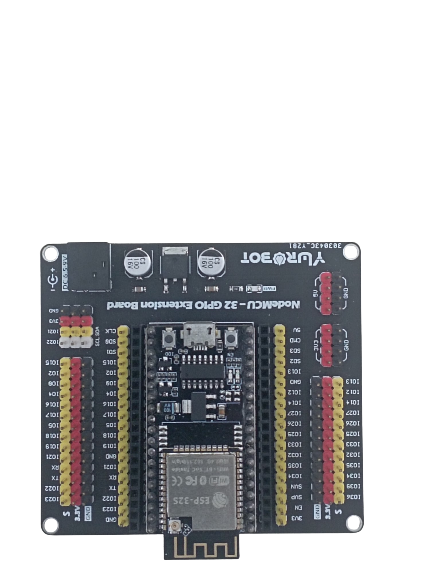
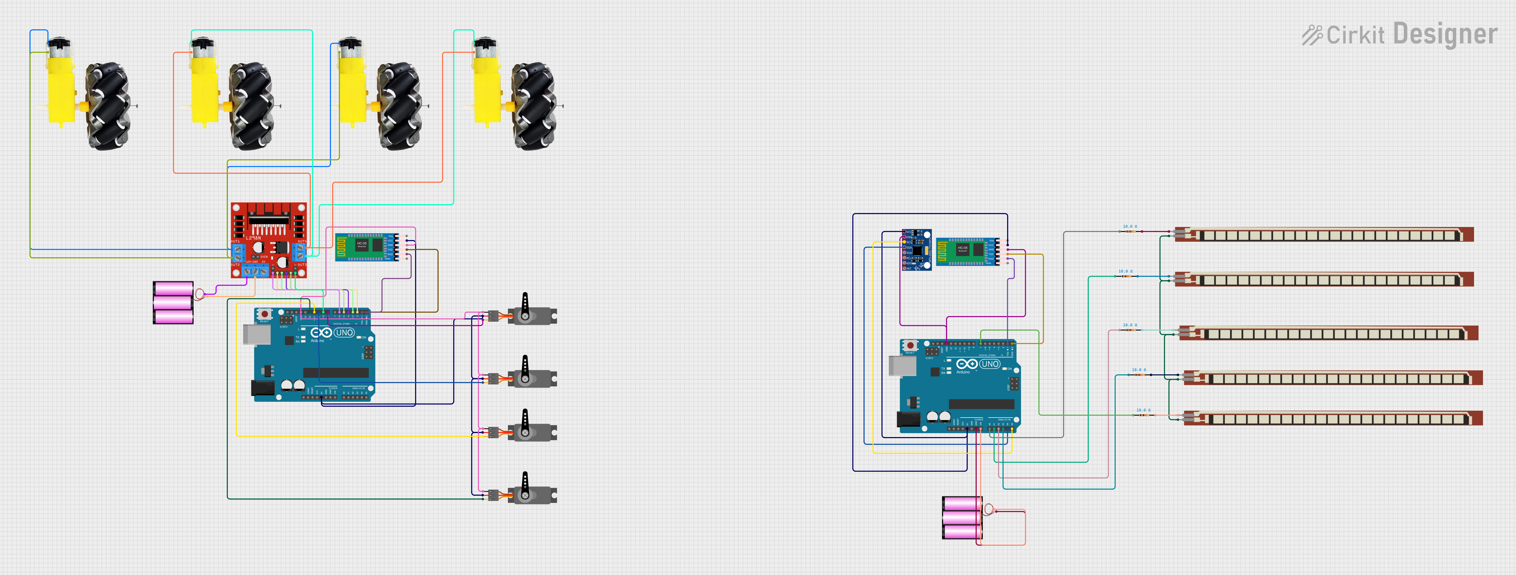
YUROBOT is a versatile robotic platform designed for educational and research purposes. It is equipped with programmable capabilities and a variety of sensors, making it ideal for interaction, automation, and experimentation. YUROBOT is widely used in robotics education, prototyping, and research projects due to its modular design and ease of integration with microcontrollers like Arduino.
Explore Projects Built with YUROBOT
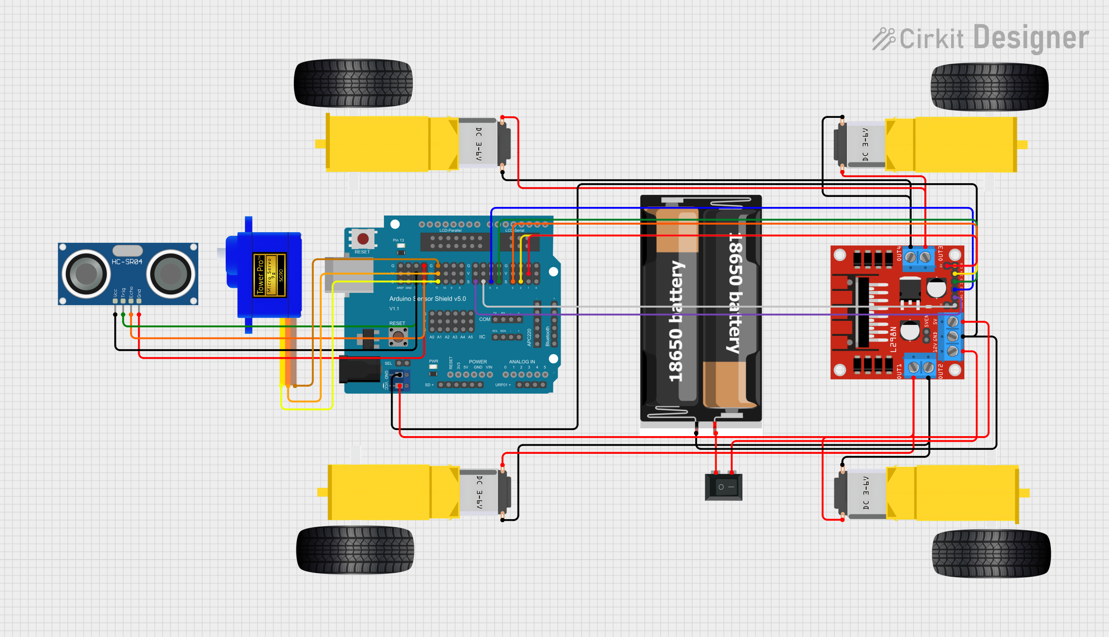
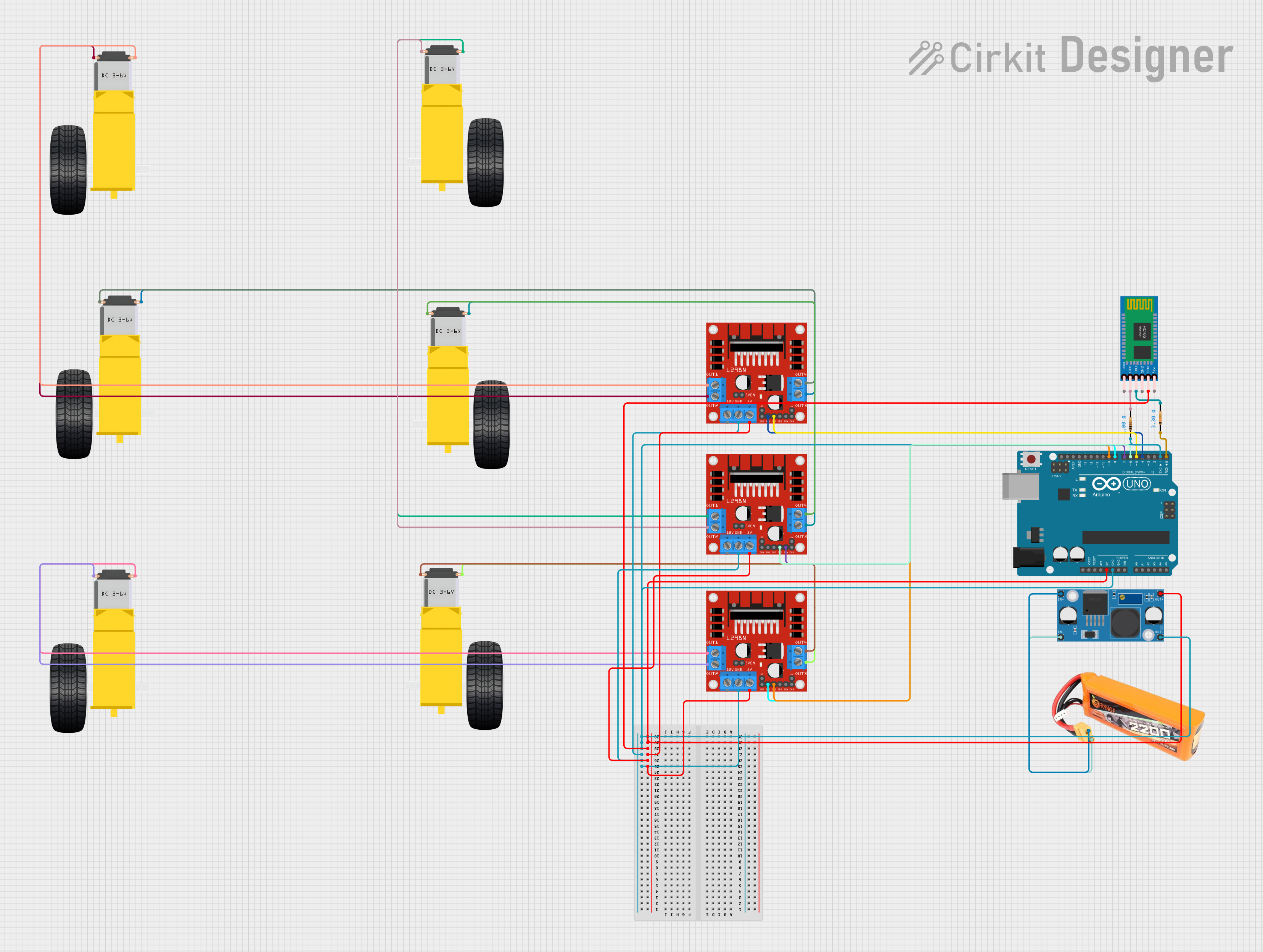
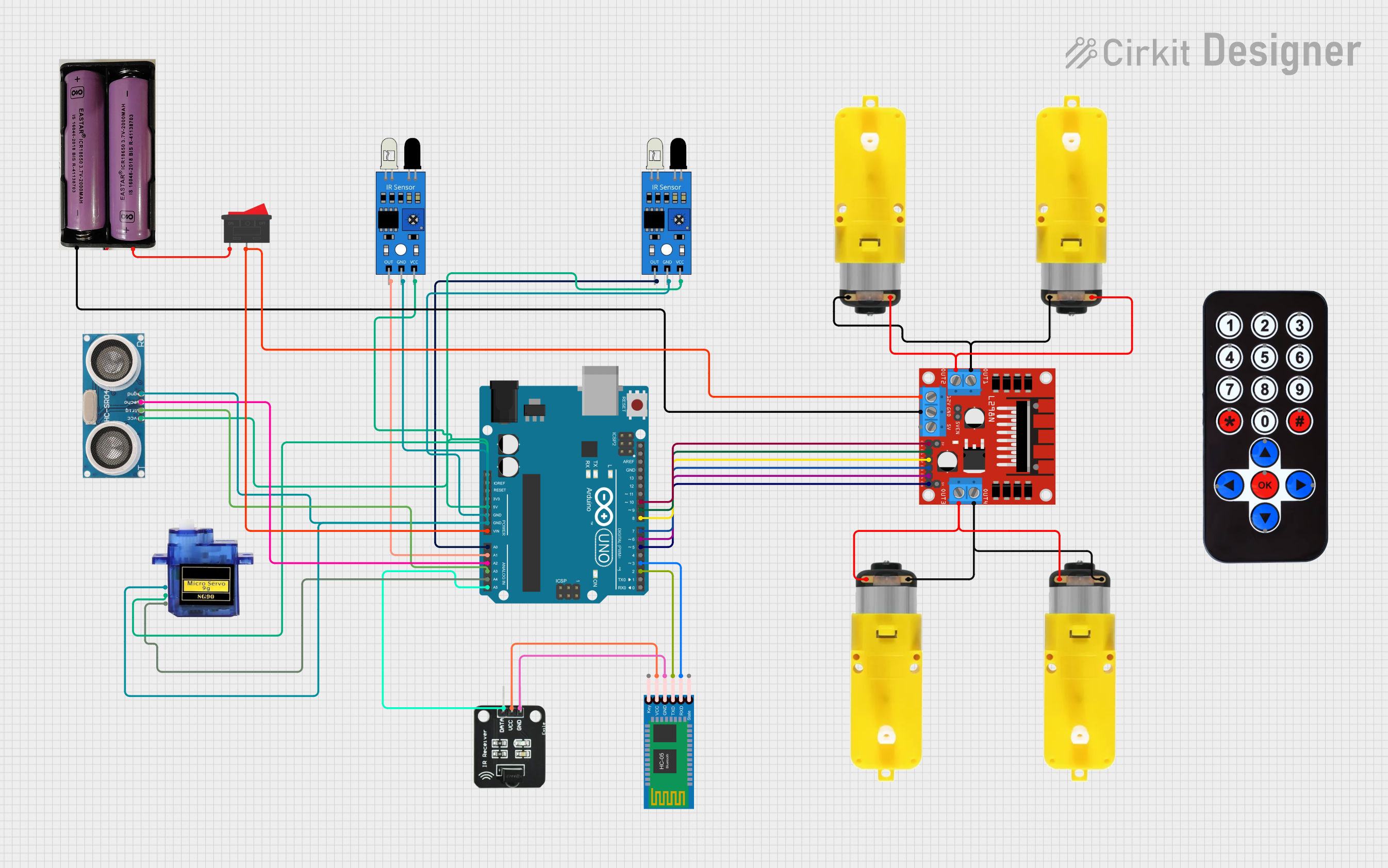
Explore Projects Built with YUROBOT
Common Applications and Use Cases
- Robotics education and training
- Autonomous navigation and obstacle avoidance
- Sensor-based data collection and analysis
- Prototyping robotic systems
- Research in automation and artificial intelligence
Technical Specifications
Below are the key technical details and pin configurations for YUROBOT:
Key Technical Details
| Parameter | Specification |
|---|---|
| Operating Voltage | 5V - 12V |
| Motor Driver | Dual H-Bridge Motor Driver (L298N) |
| Microcontroller Support | Arduino, Raspberry Pi, and others |
| Sensors | Ultrasonic, IR, Line Tracking, etc. |
| Communication Protocols | I2C, UART, SPI |
| Dimensions | 200mm x 150mm x 80mm |
| Weight | 500g |
Pin Configuration and Descriptions
Motor Driver (L298N) Pinout
| Pin Name | Description |
|---|---|
| IN1 | Input pin for Motor A |
| IN2 | Input pin for Motor A |
| IN3 | Input pin for Motor B |
| IN4 | Input pin for Motor B |
| ENA | Enable pin for Motor A (PWM control) |
| ENB | Enable pin for Motor B (PWM control) |
| VCC | Power supply for motors (5V-12V) |
| GND | Ground connection |
| 5V | Logic voltage supply for the motor driver |
Ultrasonic Sensor Pinout (HC-SR04)
| Pin Name | Description |
|---|---|
| VCC | Power supply (5V) |
| GND | Ground connection |
| TRIG | Trigger pin for sending ultrasonic pulses |
| ECHO | Echo pin for receiving reflected pulses |
Line Tracking Sensor Pinout
| Pin Name | Description |
|---|---|
| VCC | Power supply (3.3V-5V) |
| GND | Ground connection |
| OUT | Digital output signal (HIGH/LOW) |
Usage Instructions
How to Use YUROBOT in a Circuit
- Power Supply: Connect the YUROBOT to a power source within the range of 5V to 12V. Ensure the power supply is stable to avoid damage to the components.
- Microcontroller Connection: Use jumper wires to connect the motor driver and sensors to the microcontroller (e.g., Arduino UNO). Refer to the pin configuration tables for proper connections.
- Programming: Write and upload code to the microcontroller to control the motors and read sensor data. Use libraries for easier integration (e.g.,
NewPingfor ultrasonic sensors). - Testing: Test the connections and functionality of the motors and sensors before deploying the robot.
Important Considerations and Best Practices
- Power Management: Use a separate power source for motors if they draw significant current to avoid voltage drops.
- Sensor Placement: Position sensors like ultrasonic and line tracking modules carefully for optimal performance.
- PWM Control: Use PWM signals on the ENA and ENB pins to control motor speed.
- Avoid Overloading: Do not exceed the maximum current rating of the motor driver (2A per channel).
Example Code for Arduino UNO
Below is an example code to control YUROBOT's motors and read data from an ultrasonic sensor:
// Include the NewPing library for ultrasonic sensor
#include <NewPing.h>

// Define motor driver pins
#define IN1 8
#define IN2 9
#define ENA 10
#define IN3 11
#define IN4 12
#define ENB 13

// Define ultrasonic sensor pins
#define TRIG_PIN 6
#define ECHO_PIN 7

// Define maximum distance for ultrasonic sensor
#define MAX_DISTANCE 200

// Create a NewPing object
NewPing sonar(TRIG_PIN, ECHO_PIN, MAX_DISTANCE);

void setup() {
  // Initialize motor driver pins as outputs
  pinMode(IN1, OUTPUT);
  pinMode(IN2, OUTPUT);
  pinMode(ENA, OUTPUT);
  pinMode(IN3, OUTPUT);
  pinMode(IN4, OUTPUT);
  pinMode(ENB, OUTPUT);

  // Set initial motor states to LOW
  digitalWrite(IN1, LOW);
  digitalWrite(IN2, LOW);
  digitalWrite(IN3, LOW);
  digitalWrite(IN4, LOW);

  // Initialize serial communication
  Serial.begin(9600);
}

void loop() {
  // Read distance from ultrasonic sensor
  unsigned int distance = sonar.ping_cm();

  // Print distance to the Serial Monitor
  Serial.print("Distance: ");
  Serial.print(distance);
  Serial.println(" cm");

  // Example motor control: Move forward if distance > 20 cm
  if (distance > 20) {
    digitalWrite(IN1, HIGH); // Motor A forward
    digitalWrite(IN2, LOW);
    analogWrite(ENA, 150);  // Set speed for Motor A

    digitalWrite(IN3, HIGH); // Motor B forward
    digitalWrite(IN4, LOW);
    analogWrite(ENB, 150);  // Set speed for Motor B
  } else {
    // Stop motors if obstacle is too close
    digitalWrite(IN1, LOW);
    digitalWrite(IN2, LOW);
    digitalWrite(IN3, LOW);
    digitalWrite(IN4, LOW);
  }

  // Small delay for stability
  delay(100);
}
Troubleshooting and FAQs
Common Issues and Solutions
Motors Not Running
- Cause: Incorrect wiring or insufficient power supply.
- Solution: Double-check motor driver connections and ensure the power supply meets the voltage and current requirements.
Ultrasonic Sensor Not Detecting Objects
- Cause: Misaligned sensor or incorrect wiring.
- Solution: Ensure the TRIG and ECHO pins are connected properly and the sensor is facing the target object.
Line Tracking Sensor Not Responding
- Cause: Improper sensor placement or insufficient contrast.
- Solution: Adjust the sensor's height and ensure there is a clear contrast between the line and the background.
Robot Behaving Erratically
- Cause: Noise in the power supply or incorrect code logic.
- Solution: Use capacitors to filter noise and review the code for logical errors.
FAQs
Q: Can YUROBOT be used with Raspberry Pi?
A: Yes, YUROBOT is compatible with Raspberry Pi. You can use GPIO pins to control the motor driver and sensors.
Q: What is the maximum load capacity of YUROBOT?
A: YUROBOT can handle a payload of up to 1kg, depending on the motor specifications.
Q: How do I calibrate the line tracking sensors?
A: Place the robot on the track and adjust the sensor's sensitivity using the onboard potentiometer until it detects the line accurately.
Q: Can I add additional sensors to YUROBOT?
A: Yes, YUROBOT's modular design allows for easy integration of additional sensors using available GPIO pins.