How to Use WiFi Lora 32V3: Examples, Pinouts, and Specs
Introduction
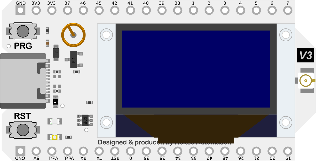
The WiFi LoRa 32(V3) is a versatile microcontroller development board that integrates WiFi and LoRa connectivity, making it an ideal choice for Internet of Things (IoT) projects. This board is based on the ESP32 chip and offers a rich set of features including long-range communication, low-power consumption, and a dual-core processor. Common applications include remote sensor networks, home automation, and smart agriculture.
Explore Projects Built with WiFi Lora 32V3

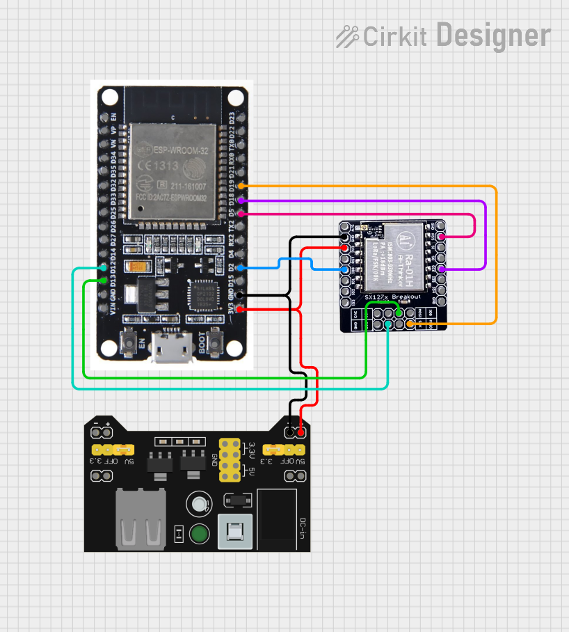
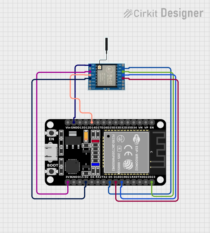

Explore Projects Built with WiFi Lora 32V3
Technical Specifications
Key Technical Details
- Microcontroller: ESP32
- Operating Voltage: 3.3V
- Input Voltage (recommended): 5V via micro USB
- Digital I/O Pins: 22
- Analog Input Pins: 6 (VP, VN, 32, 33, 34, 35)
- Clock Speed: 240 MHz
- Flash Memory: 4 MB
- SRAM: 520 KB
- Wi-Fi: 802.11 b/g/n
- LoRa: Semtech SX1276 (868 MHz/915 MHz)
- Bluetooth: v4.2 BR/EDR and BLE
Pin Configuration and Descriptions
| Pin Number | Function | Description |
|---|---|---|
| 1 | GND | Ground |
| 2 | 3V3 | 3.3V power supply |
| 3-8 | GPIO 21-26 | General Purpose Input/Output pins |
| 9 | VP | Analog Input (connected to a sensor VP) |
| 10 | VN | Analog Input (connected to a sensor VN) |
| 11-16 | GPIO 13, 12, 14, 27, 33, 32 | General Purpose Input/Output pins |
| 17 | 5V | 5V power supply (input via USB or Vin pin) |
| 18 | GND | Ground |
| 19 | RX0 | UART Receive pin |
| 20 | TX0 | UART Transmit pin |
| 21 | GND | Ground |
| 22 | 3V3 | 3.3V power supply |
Note: This is a simplified pinout for general reference. Please consult the board's datasheet for a complete pinout and pin functions.
Usage Instructions
Integrating with a Circuit
To use the WiFi LoRa 32(V3) in a circuit:
- Connect the board to your computer using a micro USB cable to provide power and programming capability.
- Ensure that the input voltage does not exceed the recommended 5V to prevent damage.
- Utilize the GPIO pins for interfacing with sensors, actuators, and other peripherals.
- The onboard LoRa and WiFi modules can be used for wireless communication.
Important Considerations and Best Practices
- Always disconnect the board from power sources before making or altering connections.
- Use a logic level converter if you need to interface with components that operate at a different voltage.
- When using LoRa, ensure that you are complying with local regulations regarding radio transmission.
- To minimize power consumption, especially in battery-powered applications, utilize the deep sleep modes provided by the ESP32.
Troubleshooting and FAQs
Common Issues
- Board not recognized by computer: Ensure the micro USB cable is data-capable and the board's drivers are installed.
- LoRa communication failure: Verify the antenna is properly connected and the frequency settings match the regional standards.
- WiFi connectivity issues: Check the SSID and password, and ensure the board is within range of the router.
Solutions and Tips for Troubleshooting
- If the board is not recognized, try a different USB port or cable and ensure the correct drivers are installed.
- For LoRa issues, double-check your code for correct initialization of frequency and spreading factor.
- For WiFi problems, ensure that your code correctly handles WiFi connection and reconnection logic.
FAQs
Q: Can I use the WiFi LoRa 32(V3) with the Arduino IDE? A: Yes, you can program the board using the Arduino IDE by installing the ESP32 add-on.
Q: What is the range of the LoRa communication? A: LoRa communication can reach several kilometers in open areas with line-of-sight conditions.
Q: How do I put the ESP32 into deep sleep mode?
A: You can use the esp_sleep_enable_timer_wakeup(time_in_us) function and then call esp_deep_sleep_start().
Example Code for Arduino UNO
Below is an example code snippet for initializing the LoRa module on the WiFi LoRa 32(V3). This code is intended for use with the Arduino IDE.
#include <SPI.h>
#include <LoRa.h>

// Define the pins used by the LoRa transceiver module
#define SCK     5    // GPIO5  -- SX1278's SCK
#define MISO    19   // GPIO19 -- SX1278's MISO
#define MOSI    27   // GPIO27 -- SX1278's MOSI
#define SS      18   // GPIO18 -- SX1278's CS
#define RST     14   // GPIO14 -- SX1278's RESET
#define DI0     26   // GPIO26 -- SX1278's IRQ(Interrupt Request)

void setup() {
  Serial.begin(9600);
  while (!Serial);

  Serial.println("LoRa Sender");

  // Setup LoRa transceiver module with the pins
  LoRa.setPins(SS, RST, DI0);

  if (!LoRa.begin(915E6)) { // Initialize LoRa at 915 MHz
    Serial.println("Starting LoRa failed!");
    while (1);
  }
}

void loop() {
  Serial.print("Sending packet: ");
  Serial.println(counter);

  // Send a packet
  LoRa.beginPacket();
  LoRa.print("hello ");
  LoRa.print(counter);
  LoRa.endPacket();

  counter++;
  delay(5000);
}
Note: The above code is a basic example to get started with LoRa communication. It sends a simple "hello" message followed by a counter value every 5 seconds. Make sure to adjust the frequency according to your regional standards.
This documentation provides an overview of the WiFi LoRa 32(V3) board, its technical specifications, usage instructions, troubleshooting tips, and a simple example code for getting started with LoRa communication. For more detailed information, refer to the manufacturer's datasheet and resources.