How to Use buck - boost module: Examples, Pinouts, and Specs
Introduction
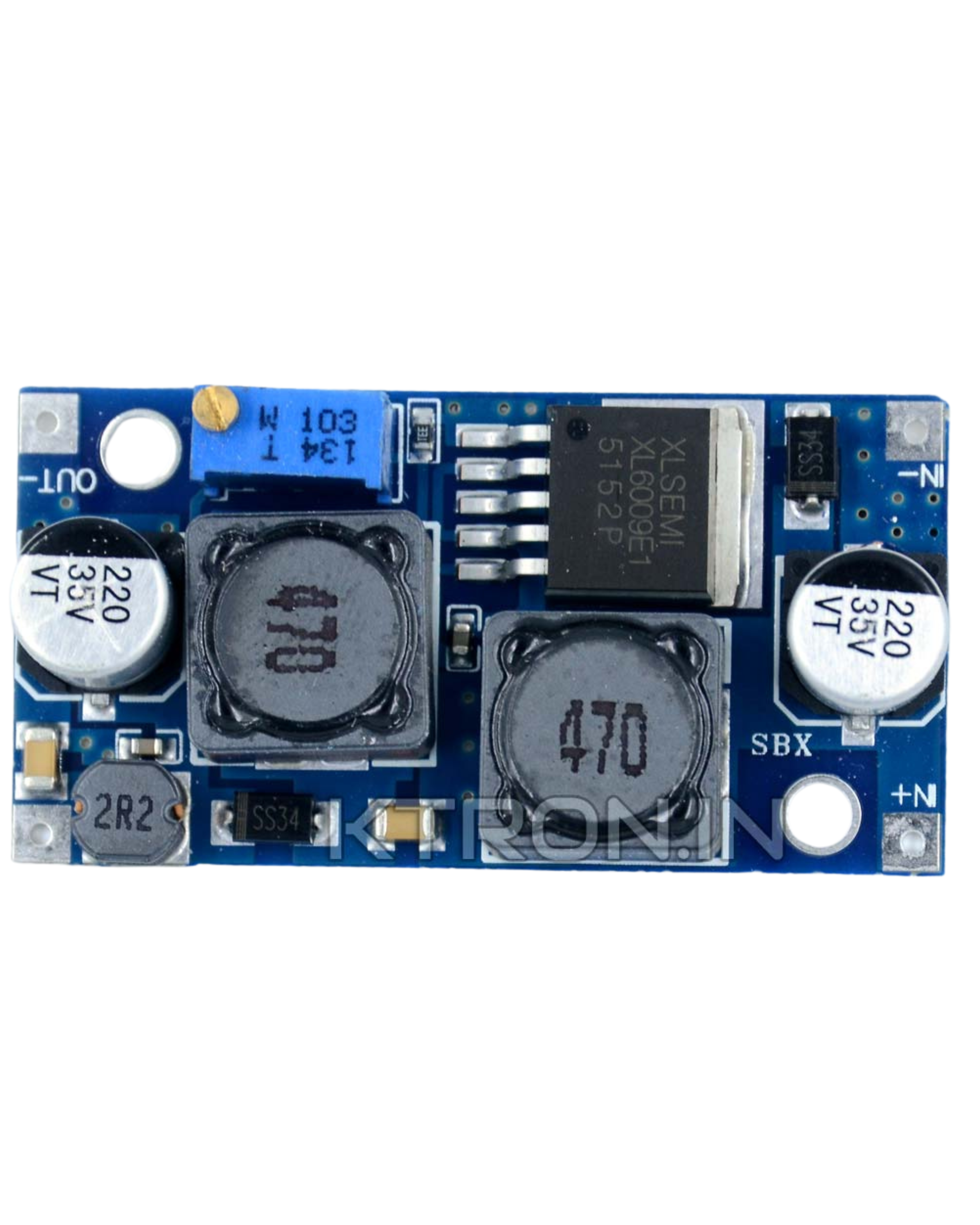
A buck-boost module is a type of DC-DC converter that can step up (boost) or step down (buck) an input voltage to a desired output voltage level. This versatility makes it an essential component in power supply applications where the input voltage may vary but a stable output voltage is required. Manufactured by Arduino with the part ID "UNO," this module is designed for seamless integration into a variety of electronic projects.
Explore Projects Built with buck - boost module


Explore Projects Built with buck - boost module
Common Applications and Use Cases
- Battery-powered devices where the input voltage fluctuates (e.g., lithium-ion batteries)
- Solar power systems to regulate voltage from solar panels
- Embedded systems requiring a stable voltage supply
- Powering microcontrollers and sensors in IoT applications
- Portable electronics and USB-powered devices
Technical Specifications
The Arduino Buck-Boost Module (Part ID: UNO) is designed to provide reliable voltage regulation with the following specifications:
Key Technical Details
| Parameter | Value |
|---|---|
| Input Voltage Range | 3V to 35V |
| Output Voltage Range | 1.25V to 35V |
| Maximum Output Current | 3A (with proper heat dissipation) |
| Efficiency | Up to 92% |
| Switching Frequency | 150 kHz |
| Operating Temperature | -40°C to +85°C |
| Dimensions | 43mm x 21mm x 14mm |
Pin Configuration and Descriptions
| Pin Name | Description |
|---|---|
| VIN+ | Positive input voltage terminal (connect to the power source) |
| VIN- | Negative input voltage terminal (connect to the ground of the power source) |
| VOUT+ | Positive output voltage terminal (connect to the load) |
| VOUT- | Negative output voltage terminal (connect to the ground of the load) |
| ADJ | Voltage adjustment pin (used to set the desired output voltage) |
Usage Instructions
How to Use the Component in a Circuit
Connect the Input Voltage:
- Connect the positive terminal of your power source to the
VIN+pin. - Connect the ground of your power source to the
VIN-pin.
- Connect the positive terminal of your power source to the
Connect the Output Voltage:
- Connect the positive terminal of your load to the
VOUT+pin. - Connect the ground of your load to the
VOUT-pin.
- Connect the positive terminal of your load to the
Adjust the Output Voltage:
- Use a small screwdriver to turn the potentiometer connected to the
ADJpin. - Turning clockwise increases the output voltage, while turning counterclockwise decreases it.
- Use a multimeter to measure the output voltage and adjust it to the desired level.
- Use a small screwdriver to turn the potentiometer connected to the
Power On:
- Once all connections are secure, power on the module by supplying input voltage within the specified range.
Important Considerations and Best Practices
- Ensure the input voltage is within the specified range (3V to 35V) to avoid damaging the module.
- Use proper heat dissipation (e.g., a heatsink) if the output current exceeds 2A to prevent overheating.
- Always measure the output voltage with a multimeter before connecting sensitive devices.
- Avoid short-circuiting the output terminals, as this may damage the module.
- For applications requiring precise voltage regulation, use a stable input power source.
Example: Connecting to an Arduino UNO
The buck-boost module can be used to power an Arduino UNO by providing a stable 5V output. Below is an example of how to connect the module and configure it:
- Set the output voltage of the buck-boost module to 5V using the
ADJpin. - Connect the
VOUT+pin of the module to the 5V pin of the Arduino UNO. - Connect the
VOUT-pin of the module to the GND pin of the Arduino UNO. - Connect the input voltage source (e.g., a 9V battery) to the
VIN+andVIN-pins of the module.
Example Code for Arduino UNO
// Example code to read a sensor powered by the buck-boost module
// Ensure the buck-boost module is set to 5V output before connecting to the Arduino

const int sensorPin = A0; // Analog pin connected to the sensor
int sensorValue = 0;      // Variable to store the sensor reading

void setup() {
  Serial.begin(9600); // Initialize serial communication at 9600 baud
  pinMode(sensorPin, INPUT); // Set the sensor pin as input
}

void loop() {
  sensorValue = analogRead(sensorPin); // Read the sensor value
  Serial.print("Sensor Value: ");
  Serial.println(sensorValue); // Print the sensor value to the Serial Monitor
  delay(1000); // Wait for 1 second before the next reading
}
Troubleshooting and FAQs
Common Issues and Solutions
No Output Voltage:
- Cause: Input voltage is not connected or is outside the specified range.
- Solution: Verify the input voltage is within 3V to 35V and check the connections.
Output Voltage is Incorrect:
- Cause: The potentiometer is not adjusted correctly.
- Solution: Use a multimeter to measure the output voltage and adjust the
ADJpin.
Module Overheating:
- Cause: Output current exceeds 2A without proper heat dissipation.
- Solution: Attach a heatsink or reduce the load current.
Fluctuating Output Voltage:
- Cause: Unstable input voltage or insufficient input filtering.
- Solution: Use a capacitor (e.g., 100µF) across the input terminals to stabilize the input voltage.
FAQs
Q: Can the module be used to charge batteries?
A: Yes, but ensure the output voltage is set to the appropriate charging voltage for the battery type.
Q: What happens if the input voltage is higher than the output voltage?
A: The module will operate in buck mode to step down the voltage.
Q: Can I use this module with a solar panel?
A: Yes, the module is suitable for solar applications. Ensure the input voltage from the solar panel is within the specified range.
Q: Is the module protected against reverse polarity?
A: No, the module does not have built-in reverse polarity protection. Always double-check the connections before powering on.