How to Use AS608: Examples, Pinouts, and Specs
Introduction
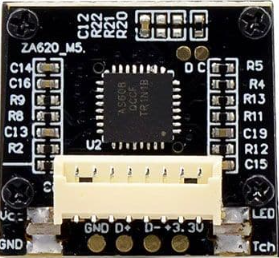
The AS608 is a fingerprint sensor module designed for biometric authentication. It features a compact design, high accuracy, and reliable performance, making it an ideal choice for secure access control systems. The module is capable of capturing, processing, and storing fingerprint data, enabling seamless integration into a wide range of electronic devices. Its ease of use and robust functionality make it suitable for applications such as door locks, safes, attendance systems, and other security-related devices.
Explore Projects Built with AS608


Explore Projects Built with AS608
Technical Specifications
- Model: AS608
- Operating Voltage: 3.3V to 6V DC
- Operating Current: < 120mA
- Interface: UART (TTL)
- Baud Rate: Configurable (default: 57600 bps)
- Fingerprint Capacity: Up to 162 fingerprints
- Image Resolution: 508 DPI
- Working Temperature: -20°C to +50°C
- Dimensions: 20mm x 20mm x 10mm (approx.)
Pin Configuration and Descriptions
The AS608 module typically has 6 pins. Below is the pinout and description:
| Pin | Name | Description |
|---|---|---|
| 1 | VCC | Power supply input (3.3V to 6V DC). |
| 2 | GND | Ground connection. |
| 3 | TXD | UART Transmit pin. Sends data to the microcontroller. |
| 4 | RXD | UART Receive pin. Receives data from the microcontroller. |
| 5 | TOUCH | Touch signal pin. Detects when the sensor is touched (optional, not always used). |
| 6 | NC | Not connected (reserved for future use). |
Usage Instructions
How to Use the AS608 in a Circuit
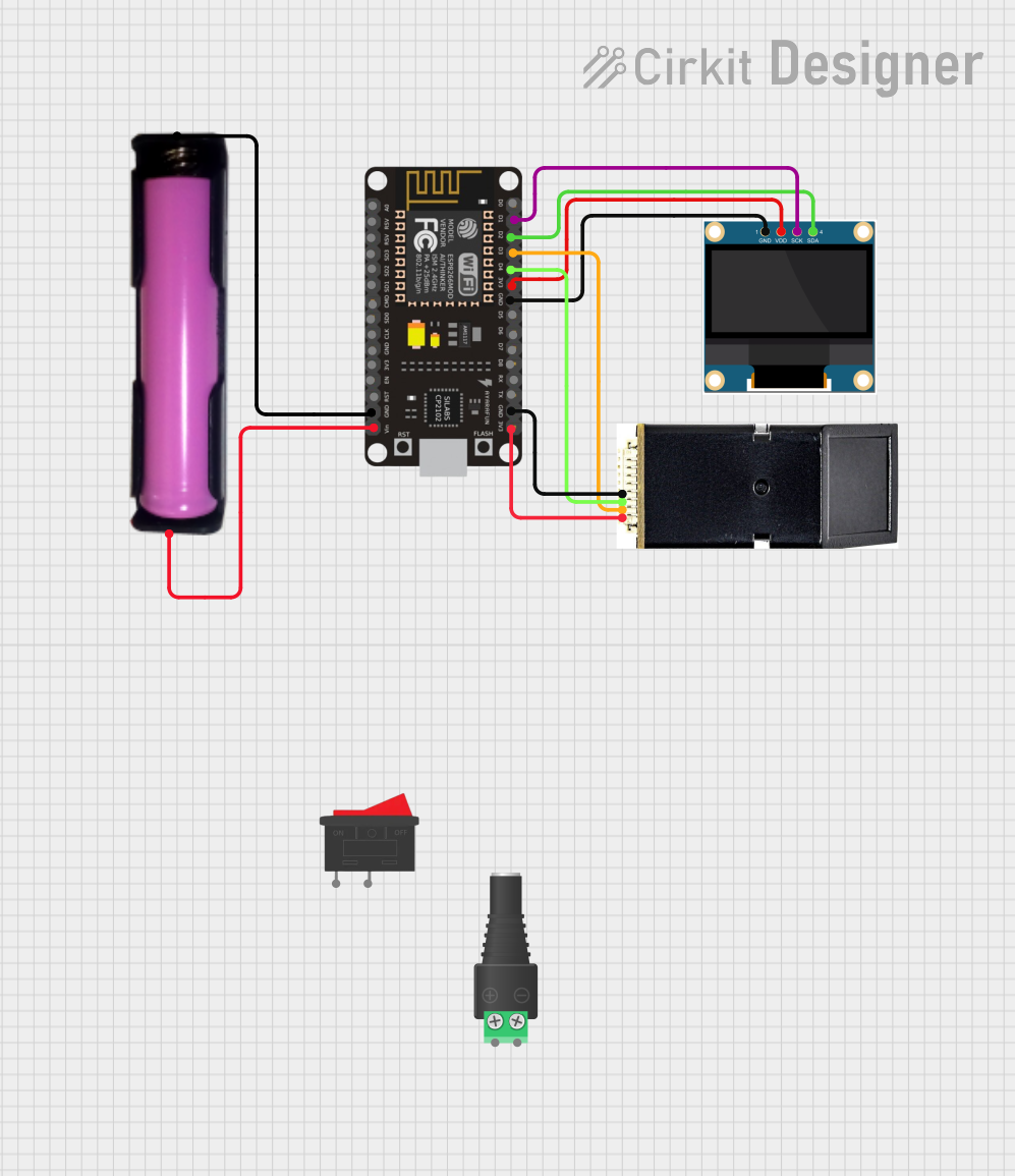
- Power Supply: Connect the VCC pin to a 3.3V or 5V power source and the GND pin to the ground.
- UART Communication: Connect the TXD and RXD pins to the corresponding UART pins on your microcontroller (e.g., Arduino UNO).
- Touch Signal (Optional): If your application requires touch detection, connect the TOUCH pin to a GPIO pin on your microcontroller.
- Library and Code: Use a compatible library (e.g., Adafruit Fingerprint Sensor Library) to simplify communication with the AS608.
Important Considerations and Best Practices
- Ensure the power supply is stable and within the specified voltage range to avoid damage to the module.
- Avoid exposing the sensor to direct sunlight or dusty environments, as this may affect its accuracy.
- When enrolling fingerprints, ensure the finger is clean and placed firmly on the sensor for optimal results.
- Use a level shifter if connecting the AS608 to a 3.3V microcontroller to avoid voltage mismatches.
Example Code for Arduino UNO
Below is an example of how to use the AS608 with an Arduino UNO to enroll and verify fingerprints:
#include <Adafruit_Fingerprint.h> // Include the Adafruit library for AS608

// Define the pins for UART communication
#define RX_PIN 2 // Pin connected to AS608 TXD
#define TX_PIN 3 // Pin connected to AS608 RXD

// Create a fingerprint sensor object
Adafruit_Fingerprint finger(&mySerial);

// Initialize software serial for communication
SoftwareSerial mySerial(RX_PIN, TX_PIN);

void setup() {
  Serial.begin(9600); // Start serial communication with the PC
  mySerial.begin(57600); // Start communication with the AS608 module

  // Initialize the fingerprint sensor
  if (finger.begin()) {
    Serial.println("Fingerprint sensor initialized successfully!");
  } else {
    Serial.println("Failed to initialize fingerprint sensor. Check connections.");
    while (1); // Halt the program if initialization fails
  }
}

void loop() {
  Serial.println("Place your finger on the sensor...");
  if (finger.getImage() == FINGERPRINT_OK) {
    Serial.println("Fingerprint image captured!");
    // Additional code for processing the fingerprint can be added here
  } else {
    Serial.println("Failed to capture fingerprint. Try again.");
  }
}
Notes:
- Install the Adafruit Fingerprint Sensor Library from the Arduino Library Manager before running the code.
- Modify the
RX_PINandTX_PINdefinitions if using different pins for UART communication.
Troubleshooting and FAQs
Common Issues and Solutions
The sensor does not initialize:
- Ensure the VCC and GND connections are secure and the power supply is within the specified range.
- Verify the TXD and RXD connections. Ensure they are not swapped.
- Check the baud rate configuration in the code. The default is 57600 bps.
Fingerprint not detected:
- Ensure the finger is clean and placed properly on the sensor.
- Avoid moving the finger during the scanning process.
- Clean the sensor surface with a soft, lint-free cloth if it appears dirty.
Communication errors:
- Verify the UART connections and ensure the correct pins are used.
- Check for loose wires or poor soldering on the connections.
FAQs
Q: Can the AS608 store multiple fingerprints?
A: Yes, the AS608 can store up to 162 fingerprints in its internal memory.
Q: Is the AS608 compatible with 3.3V microcontrollers?
A: Yes, the AS608 works with both 3.3V and 5V systems. However, ensure proper voltage levels for UART communication.
Q: How do I reset the AS608 module?
A: You can reset the module by sending a reset command via UART or by power cycling the module.
Q: Can the AS608 be used outdoors?
A: While the AS608 is robust, it is recommended to use it in controlled environments to ensure accuracy and longevity. Avoid direct sunlight and excessive dust.