How to Use 5643AS 7-segment display: Examples, Pinouts, and Specs
Introduction
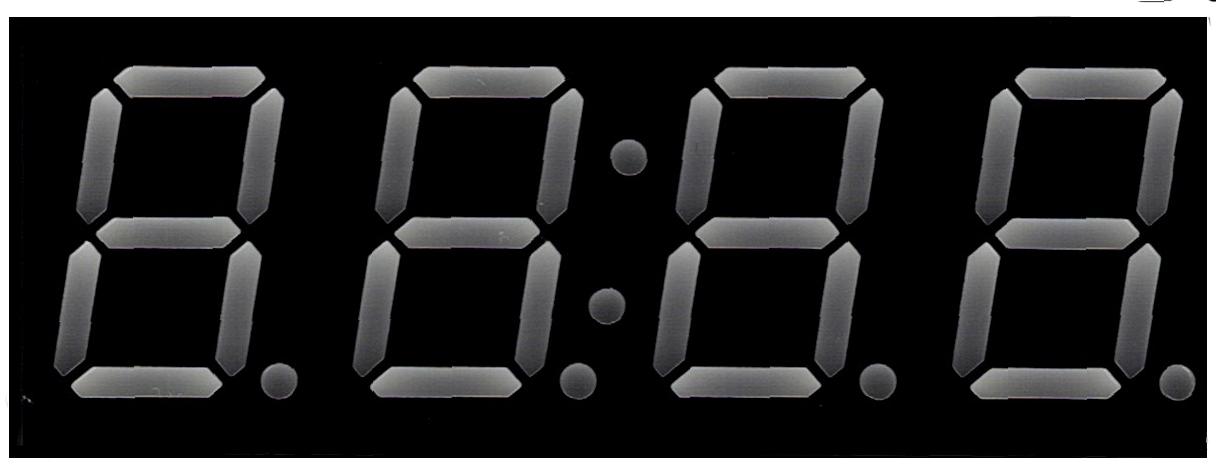
The 5643AS is a 7-segment display commonly used in electronic projects for displaying numerical information. Each segment consists of a single LED, and by controlling which LEDs are lit, it can represent the numbers 0 through 9. This component is widely used in digital clocks, electronic meters, and other devices that require a simple numeric display.
Explore Projects Built with 5643AS 7-segment display

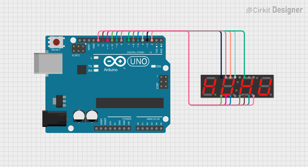
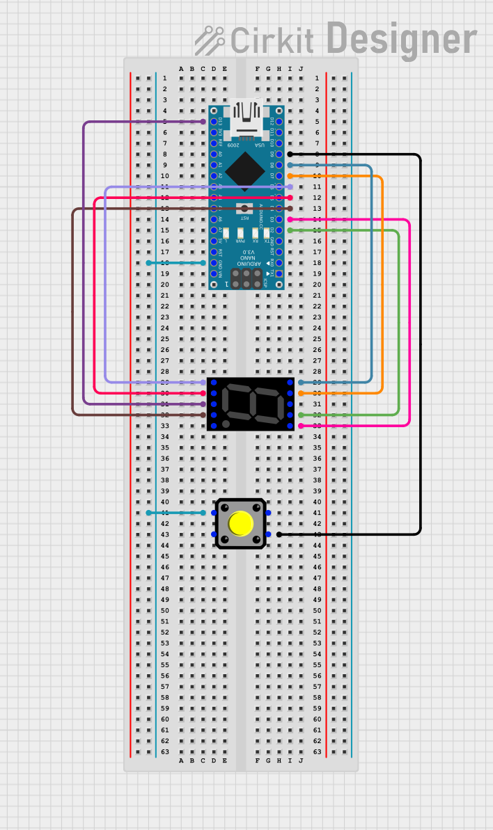
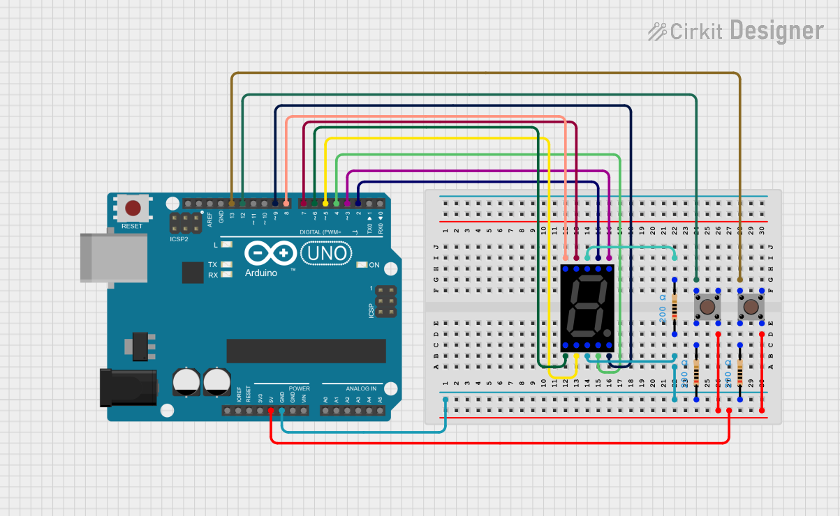
Explore Projects Built with 5643AS 7-segment display
Common Applications
- Digital clocks
- Electronic counters
- Calculators
- Timers
- User interfaces for electronic devices
Technical Specifications
Key Technical Details
- Display Type: Common Anode 7-Segment
- Operating Voltage: 2.0V to 2.5V
- Max Forward Current: 20mA per segment
- Max Reverse Voltage: 5V
- Luminous Intensity: 80-100 mcd
- Wavelength: 625-630 nm (Red)
Pin Configuration and Descriptions
| Pin Number | Segment | Description |
|---|---|---|
| 1 | E | Controls the bottom-left LED segment |
| 2 | D | Controls the bottom LED segment |
| 3 | Common Anode | Connected to the positive voltage supply |
| 4 | C | Controls the bottom-right LED segment |
| 5 | DP | Controls the decimal point LED |
| 6 | B | Controls the top-right LED segment |
| 7 | A | Controls the top LED segment |
| 8 | F | Controls the top-left LED segment |
| 9 | G | Controls the middle LED segment |
| 10 | Common Anode | Connected to the positive voltage supply |
Usage Instructions
How to Use the Component in a Circuit
- Connect the common anode pins (3 and 10) to the positive voltage supply.
- Connect each of the segment pins (A-G and DP) through a current-limiting resistor to the digital output pins of a microcontroller or other control logic.
- To display a number, activate the corresponding segments by setting the control pins to LOW (for a common anode display).
Important Considerations and Best Practices
- Always use current-limiting resistors with each segment to prevent damage to the LEDs.
- Ensure that the power supply voltage does not exceed the maximum forward voltage of the segments.
- To increase the lifespan of the display, avoid operating at the maximum forward current continuously.
- Multiplexing can be used to control multiple displays with fewer microcontroller pins.
Example Code for Arduino UNO
// Define the Arduino pins connected to the segments A-G and DP
const int segA = 2;
const int segB = 3;
const int segC = 4;
const int segD = 5;
const int segE = 6;
const int segF = 7;
const int segG = 8;
const int segDP = 9;

// Define the digit to segment mapping for common anode displays
int digits[10][7] = {
  {0,0,0,0,0,0,1}, // 0
  {1,0,0,1,1,1,1}, // 1
  {0,0,1,0,0,1,0}, // 2
  {0,0,0,0,1,1,0}, // 3
  {1,0,0,1,1,0,0}, // 4
  {0,1,0,0,1,0,0}, // 5
  {0,1,0,0,0,0,0}, // 6
  {0,0,0,1,1,1,1}, // 7
  {0,0,0,0,0,0,0}, // 8
  {0,0,0,0,1,0,0}  // 9
};

void setup() {
  // Set all the segment pins as outputs
  pinMode(segA, OUTPUT);
  pinMode(segB, OUTPUT);
  pinMode(segC, OUTPUT);
  pinMode(segD, OUTPUT);
  pinMode(segE, OUTPUT);
  pinMode(segF, OUTPUT);
  pinMode(segG, OUTPUT);
  pinMode(segDP, OUTPUT);
}

void loop() {
  for (int digit = 0; digit < 10; digit++) {
    displayDigit(digit);
    delay(1000); // Display each number for 1 second
  }
}

// Function to display a single digit on the 7-segment display
void displayDigit(int digit) {
  int *segments = digits[digit];
  digitalWrite(segA, segments[0]);
  digitalWrite(segB, segments[1]);
  digitalWrite(segC, segments[2]);
  digitalWrite(segD, segments[3]);
  digitalWrite(segE, segments[4]);
  digitalWrite(segF, segments[5]);
  digitalWrite(segG, segments[6]);
  // Note: DP is not used in this example, but can be controlled similarly
}
Troubleshooting and FAQs
Common Issues
- Segments not lighting up: Check the connections and ensure that the common anode is connected to the positive supply and that the segment pins are connected through current-limiting resistors.
- Dim segments: Ensure that the power supply voltage is within the recommended range and that the current-limiting resistors are of the correct value.
- Segments always on: Verify that the control logic is correctly implemented and that the microcontroller pins are functioning properly.
Solutions and Tips for Troubleshooting
- Double-check wiring against the pin configuration table.
- Measure the voltage across each segment to ensure it is within the operating range.
- Replace current-limiting resistors if they are not the correct value.
- Test each segment individually to isolate any issues.
FAQs
Q: Can I use a 5643AS display with a 5V Arduino? A: Yes, but ensure you use appropriate current-limiting resistors to protect the LEDs.
Q: How can I control multiple 7-segment displays? A: You can use multiplexing or a dedicated driver IC to control multiple displays with a limited number of microcontroller pins.
Q: What is the purpose of the decimal point (DP)? A: The DP can be used to display decimal points in numbers, useful in applications like digital clocks or readouts that require a decimal point.