
How to Use ROTARY SWITCH: Examples, Pinouts, and Specs
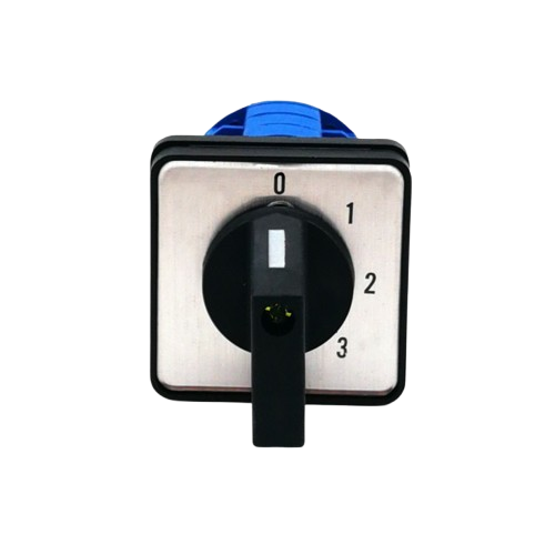
 Design with ROTARY SWITCH in Cirkit Designer
Introduction
A rotary switch is an electrical switch that is operated by rotating a knob or shaft. It allows the user to select different circuits or functions by turning the switch to different positions. Rotary switches are commonly used in applications where multiple circuit options or settings need to be selected manually. They are versatile and reliable components found in devices such as audio equipment, industrial machinery, and control panels.
Explore Projects Built with ROTARY SWITCH
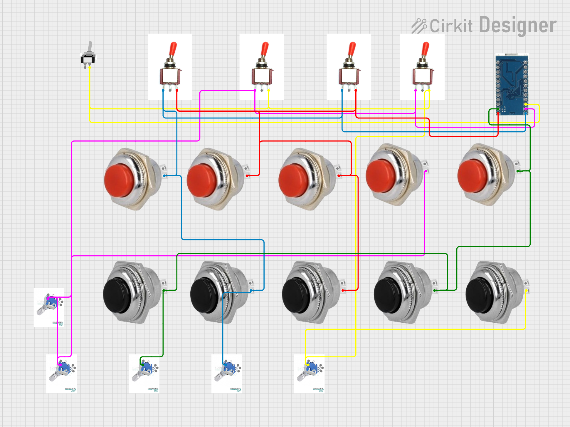 Open Project in Cirkit Designer
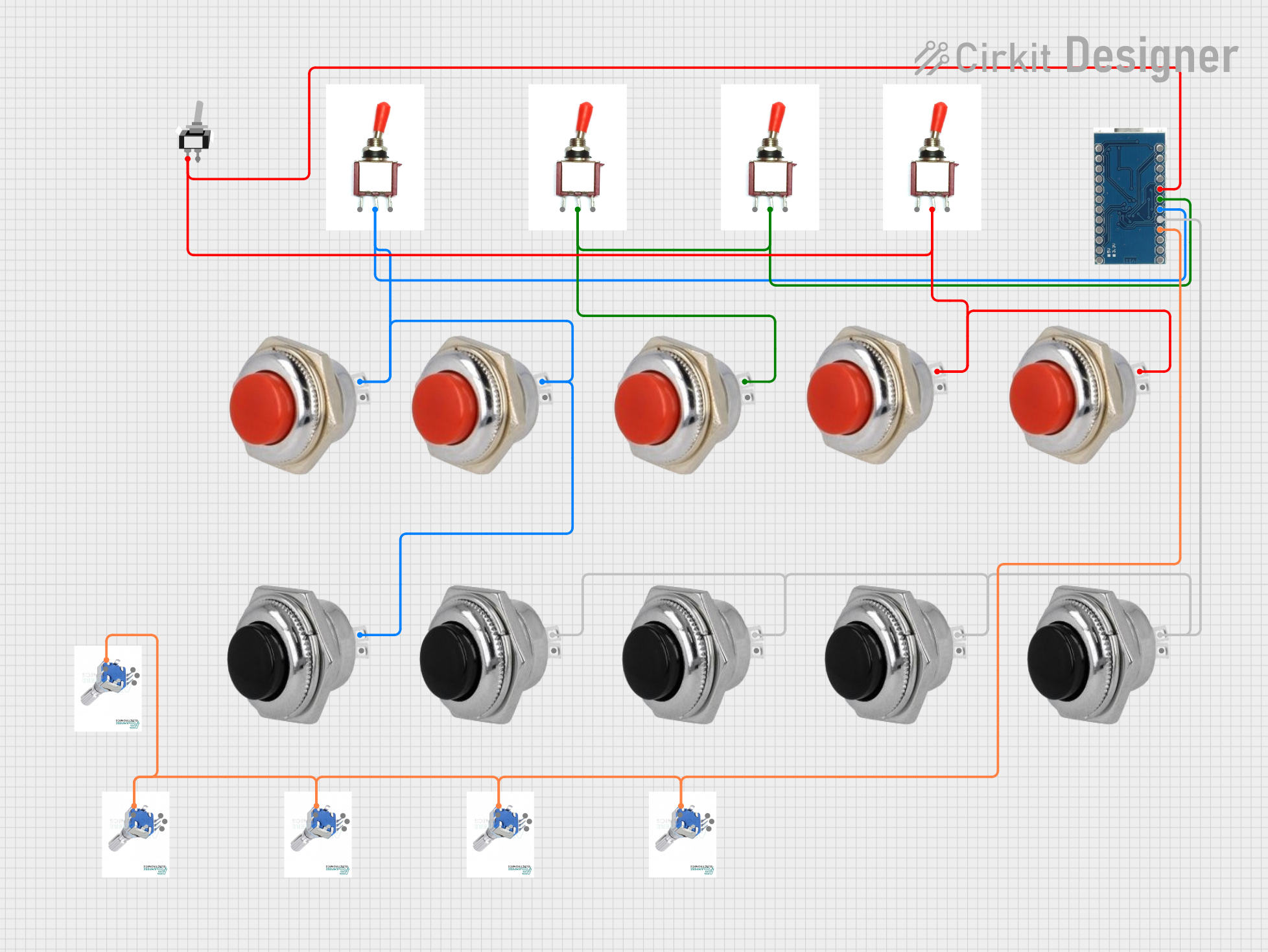 Open Project in Cirkit Designer
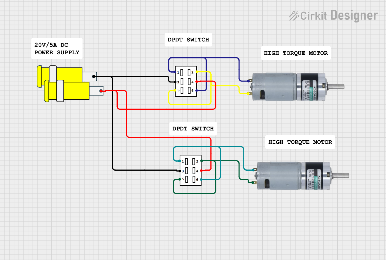 Open Project in Cirkit Designer
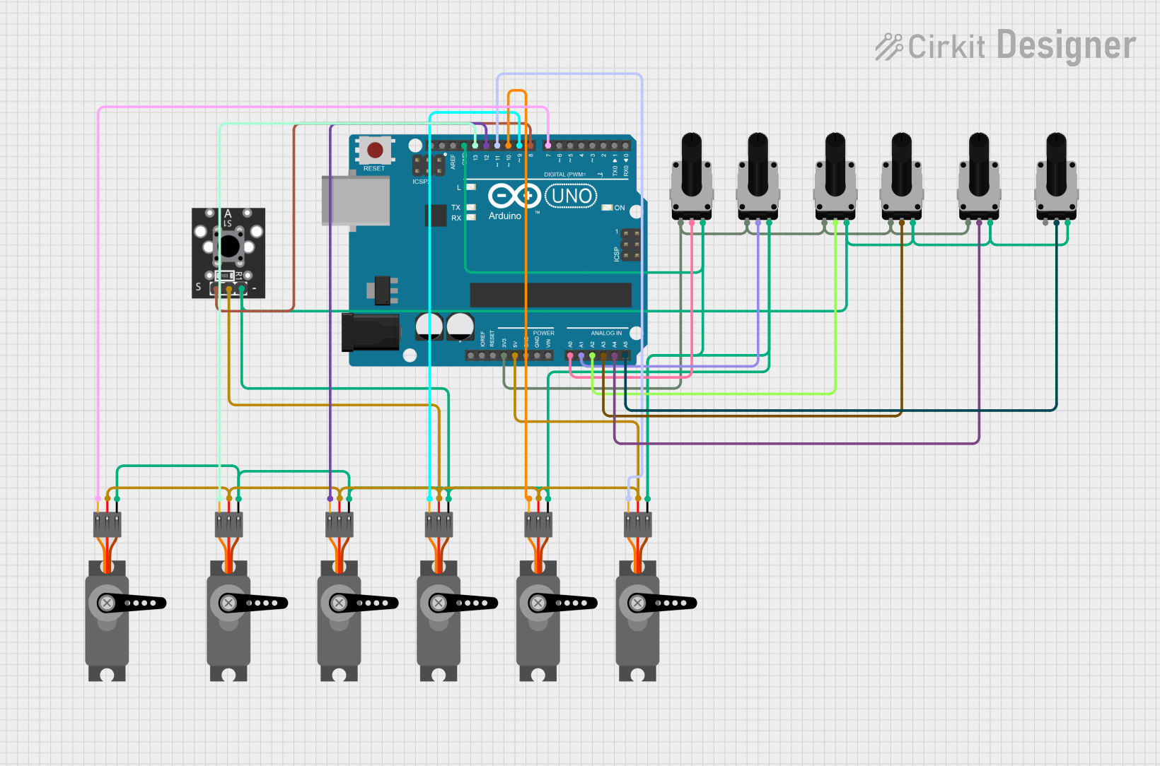 Open Project in Cirkit Designer
Explore Projects Built with ROTARY SWITCH
Open Project in Cirkit DesignerOpen Project in Cirkit DesignerOpen Project in Cirkit DesignerOpen Project in Cirkit DesignerCommon Applications and Use Cases
- Audio equipment for selecting input sources or adjusting settings
- Industrial control panels for mode or function selection
- Test and measurement equipment
- Home appliances, such as ovens or washing machines
- Radio frequency (RF) applications for selecting frequency bands
Technical Specifications
Below are the general technical specifications for a typical rotary switch. Note that specific values may vary depending on the model and manufacturer.
| Parameter | Specification |
|---|---|
| Voltage Rating | 12V to 250V (AC or DC, depending on model) |
| Current Rating | 0.3A to 6A |
| Number of Positions | 2 to 12 (or more, depending on design) |
| Contact Resistance | < 50 mΩ |
| Insulation Resistance | > 100 MΩ |
| Operating Temperature | -20°C to 85°C |
| Mechanical Life | 10,000 to 50,000 cycles |
Pin Configuration and Descriptions
The pin configuration of a rotary switch depends on the number of positions and poles. Below is an example for a single-pole, 4-position rotary switch:
| Pin Number | Description |
|---|---|
| 1 | Common terminal (COM) |
| 2 | Position 1 output |
| 3 | Position 2 output |
| 4 | Position 3 output |
| 5 | Position 4 output |
For a double-pole, 3-position rotary switch, the configuration might look like this:
| Pin Number | Description |
|---|---|
| 1 | Common terminal for Pole 1 |
| 2 | Position 1 output for Pole 1 |
| 3 | Position 2 output for Pole 1 |
| 4 | Position 3 output for Pole 1 |
| 5 | Common terminal for Pole 2 |
| 6 | Position 1 output for Pole 2 |
| 7 | Position 2 output for Pole 2 |
| 8 | Position 3 output for Pole 2 |
Usage Instructions
How to Use the Rotary Switch in a Circuit
- Identify the Common Terminal (COM): The common terminal is the central pin that connects to the selected position.
- Connect the Output Terminals: Attach the output terminals to the circuits or devices you want to control.
- Select the Number of Positions: Ensure the rotary switch has the correct number of positions for your application.
- Mount the Switch: Secure the rotary switch to your device or control panel using the provided mounting hardware.
- Test the Connections: Rotate the switch to each position and verify that the correct circuit is activated.
Important Considerations and Best Practices
- Voltage and Current Ratings: Ensure the rotary switch can handle the voltage and current of your application to avoid damage or failure.
- Debouncing: Rotary switches may produce electrical noise (bouncing) when switching positions. Use a capacitor or software debouncing techniques to mitigate this.
- Position Stops: Verify that the switch has the correct number of stops (positions) for your application.
- Wiring: Double-check all connections to avoid short circuits or incorrect operation.
- Durability: For high-use applications, select a rotary switch with a high mechanical life rating.
Example: Connecting a Rotary Switch to an Arduino UNO
Below is an example of how to connect a single-pole, 4-position rotary switch to an Arduino UNO to read its position.
Circuit Diagram
- Connect the common terminal (COM) of the rotary switch to the Arduino's GND.
- Connect each position terminal (e.g., Position 1, Position 2, etc.) to separate digital input pins on the Arduino (e.g., D2, D3, D4, D5).
- Use pull-down resistors (10kΩ) on each input pin to ensure stable readings.
Arduino Code
// Rotary Switch Example Code
// This code reads the position of a 4-position rotary switch connected to an Arduino UNO.

const int positionPins[] = {2, 3, 4, 5}; // Pins connected to the rotary switch
const int numPositions = 4;              // Number of positions on the switch

void setup() {
  Serial.begin(9600); // Initialize serial communication
  for (int i = 0; i < numPositions; i++) {
    pinMode(positionPins[i], INPUT_PULLUP); // Set pins as input with pull-up resistors
  }
}

void loop() {
  for (int i = 0; i < numPositions; i++) {
    if (digitalRead(positionPins[i]) == LOW) {
      // If the pin reads LOW, the switch is in this position
      Serial.print("Rotary Switch Position: ");
      Serial.println(i + 1); // Print the position (1-based index)
      delay(500); // Debounce delay
    }
  }
}
Troubleshooting and FAQs
Common Issues
Switch Not Working:
- Cause: Incorrect wiring or loose connections.
- Solution: Double-check the wiring and ensure all connections are secure.
Incorrect Position Detection:
- Cause: Electrical noise or bouncing.
- Solution: Add a capacitor across the common terminal and ground, or implement software debouncing.
Overheating or Damage:
- Cause: Exceeding the voltage or current rating.
- Solution: Verify that the rotary switch is rated for your application's voltage and current.
Switch Feels Stiff or Loose:
- Cause: Mechanical wear or improper installation.
- Solution: Replace the switch if worn out, or ensure it is mounted correctly.
FAQs
Q: Can I use a rotary switch for high-power applications?
A: Rotary switches are typically designed for low to moderate power applications. For high-power circuits, use a switch specifically rated for high current and voltage.
Q: How do I increase the number of positions on a rotary switch?
A: You cannot modify the number of positions on a rotary switch. Select a switch with the required number of positions during the design phase.
Q: Can a rotary switch be used for analog signals?
A: Yes, rotary switches can be used for analog signals, but ensure the switch has low contact resistance and is suitable for the signal's voltage and current levels.
Q: How do I clean a rotary switch?
A: Use a contact cleaner spray to remove dirt or oxidation from the contacts. Avoid using excessive force or abrasive materials.