How to Use EVAL-ADLX355: Examples, Pinouts, and Specs
Introduction
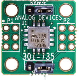
The EVAL-ADLX355 is an evaluation board designed by Analog Devices to demonstrate the capabilities of the ADLX355, a high-performance power management integrated circuit (PMIC). The ADLX355 is engineered to manage multiple power rails efficiently, making it ideal for applications requiring precise power delivery and monitoring. The evaluation board provides a convenient platform for testing, prototyping, and evaluating the ADLX355's features in a controlled environment.
Explore Projects Built with EVAL-ADLX355


Explore Projects Built with EVAL-ADLX355
Common Applications and Use Cases
- Power management in embedded systems
- Industrial automation and control systems
- Portable and battery-powered devices
- Internet of Things (IoT) devices
- Prototyping and development of multi-rail power systems
Technical Specifications
Key Technical Details
- Input Voltage Range: 2.7 V to 5.5 V
- Output Voltage Range: Configurable (dependent on ADLX355 settings)
- Maximum Output Current: Up to 3 A per rail
- Number of Power Rails: Supports up to 4 independent rails
- Efficiency: Up to 95% (depending on load conditions)
- Communication Interface: I²C-compatible
- Operating Temperature Range: -40°C to +125°C
- Board Dimensions: 50 mm x 50 mm
Pin Configuration and Descriptions
The EVAL-ADLX355 board provides several key connectors and pins for interfacing with the ADLX355. Below is a table describing the primary pin headers:
Power Input and Output Pins
| Pin Name | Description | Voltage Range | Notes |
|---|---|---|---|
| VIN | Main power input | 2.7 V to 5.5 V | Connect to an external power source |
| GND | Ground | - | Common ground for the board |
| VOUT1 | Output voltage for Rail 1 | Configurable | Adjustable via I²C |
| VOUT2 | Output voltage for Rail 2 | Configurable | Adjustable via I²C |
| VOUT3 | Output voltage for Rail 3 | Configurable | Adjustable via I²C |
| VOUT4 | Output voltage for Rail 4 | Configurable | Adjustable via I²C |
Communication and Control Pins
| Pin Name | Description | Voltage Level | Notes |
|---|---|---|---|
| SDA | I²C data line | 0 V to 3.3 V | Connect to microcontroller SDA pin |
| SCL | I²C clock line | 0 V to 3.3 V | Connect to microcontroller SCL pin |
| EN | Enable pin for the ADLX355 | 0 V to 3.3 V | Pull high to enable the IC |
| INT | Interrupt output | 0 V to 3.3 V | Signals fault or status changes |
Usage Instructions
How to Use the EVAL-ADLX355 in a Circuit
Powering the Board:
- Connect a DC power supply (2.7 V to 5.5 V) to the VIN and GND pins.
- Ensure the power supply can provide sufficient current for the connected load.
Configuring Output Voltages:
- Use the I²C interface to configure the output voltages for each rail (VOUT1 to VOUT4).
- Refer to the ADLX355 datasheet for detailed register settings.
Connecting to a Microcontroller:
- Connect the SDA and SCL pins to the corresponding I²C pins on your microcontroller.
- Pull-up resistors (typically 4.7 kΩ) may be required on the SDA and SCL lines.
Enabling the IC:
- Pull the EN pin high to enable the ADLX355.
- Monitor the INT pin for fault or status signals.
Load Connection:
- Connect your load to the appropriate output rail (VOUT1 to VOUT4).
- Ensure the load does not exceed the maximum current rating for the rail.
Important Considerations and Best Practices
- Thermal Management: Ensure adequate ventilation or heat sinking if operating at high currents.
- I²C Address: The default I²C address of the ADLX355 is configurable. Check the evaluation board documentation for details.
- Startup Sequence: Always power the board before enabling the IC to avoid damage.
- Load Testing: Gradually increase the load to verify stability and performance.
Example Code for Arduino UNO
Below is an example of how to configure the ADLX355 using an Arduino UNO via the I²C interface:
#include <Wire.h>

// Define the I²C address of the ADLX355
#define ADLX355_I2C_ADDRESS 0x3C

void setup() {
  Wire.begin(); // Initialize I²C communication
  Serial.begin(9600); // Initialize serial communication for debugging

  // Configure Rail 1 to output 3.3V
  configureRail(1, 3300); // Rail 1, 3300 mV
}

void loop() {
  // Monitor the INT pin or perform other tasks
}

// Function to configure a specific rail voltage
void configureRail(uint8_t rail, uint16_t voltage_mV) {
  uint8_t registerAddress = 0x10 + (rail - 1) * 2; // Calculate register address
  uint16_t voltageCode = voltage_mV / 10; // Convert mV to register code

  Wire.beginTransmission(ADLX355_I2C_ADDRESS);
  Wire.write(registerAddress); // Write the register address
  Wire.write((voltageCode >> 8) & 0xFF); // Write the high byte
  Wire.write(voltageCode & 0xFF); // Write the low byte
  Wire.endTransmission();

  Serial.print("Rail ");
  Serial.print(rail);
  Serial.print(" configured to ");
  Serial.print(voltage_mV);
  Serial.println(" mV");
}
Troubleshooting and FAQs
Common Issues and Solutions
No Output Voltage:
- Ensure the EN pin is pulled high.
- Verify the I²C configuration and ensure the correct address is used.
- Check the input voltage (VIN) and ensure it is within the specified range.
Overheating:
- Reduce the load current or improve thermal management.
- Verify that the output voltages are configured correctly.
I²C Communication Failure:
- Check the SDA and SCL connections and ensure pull-up resistors are in place.
- Verify the I²C address and ensure no address conflicts exist.
INT Pin Active:
- Check for fault conditions such as overcurrent or thermal shutdown.
- Use the I²C interface to read the status registers for more details.
FAQs
Can I use the EVAL-ADLX355 with a 5 V microcontroller?
- Yes, but ensure the I²C lines are level-shifted to 3.3 V to avoid damaging the ADLX355.
What is the maximum load current per rail?
- Each rail can supply up to 3 A, but ensure the total load does not exceed the board's thermal limits.
How do I reset the ADLX355?
- Power cycle the board or use the I²C interface to reset the IC via the appropriate register.
This documentation provides a comprehensive guide to using the EVAL-ADLX355 evaluation board effectively. For further details, refer to the official datasheet and user guide provided by Analog Devices.