How to Use OLED Display: 0.97-inch I2C: Examples, Pinouts, and Specs
Introduction
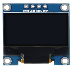
The 0.97-inch OLED Display is a compact, low-power display module that utilizes organic light-emitting diodes (OLEDs) to produce bright, high-contrast images. This display is ideal for applications requiring clear visuals in a small form factor. It communicates via the I2C interface, making it easy to integrate with microcontrollers such as Arduino, Raspberry Pi, and other development boards.
Explore Projects Built with OLED Display: 0.97-inch I2C


Explore Projects Built with OLED Display: 0.97-inch I2C
Common Applications and Use Cases
- Wearable devices
- IoT dashboards and indicators
- Portable electronics
- Sensor data visualization
- Compact user interfaces for embedded systems
Technical Specifications
The following table outlines the key technical details of the 0.97-inch OLED Display:
| Parameter | Specification |
|---|---|
| Display Type | OLED |
| Screen Size | 0.97 inches |
| Resolution | 128 x 64 pixels |
| Interface | I2C |
| Operating Voltage | 3.3V - 5V |
| Operating Current | ~20mA |
| Viewing Angle | >160° |
| Contrast Ratio | 2000:1 |
| Operating Temperature | -40°C to +85°C |
| Dimensions | 27mm x 27mm x 4mm |
Pin Configuration and Descriptions
The OLED Display module typically has a 4-pin interface for I2C communication. The pinout is as follows:
| Pin Name | Description | Notes |
|---|---|---|
| VCC | Power Supply (3.3V - 5V) | Connect to the microcontroller's power pin. |
| GND | Ground | Connect to the ground of the circuit. |
| SCL | Serial Clock Line | Connect to the I2C clock pin (e.g., A5 on Arduino UNO). |
| SDA | Serial Data Line | Connect to the I2C data pin (e.g., A4 on Arduino UNO). |
Usage Instructions
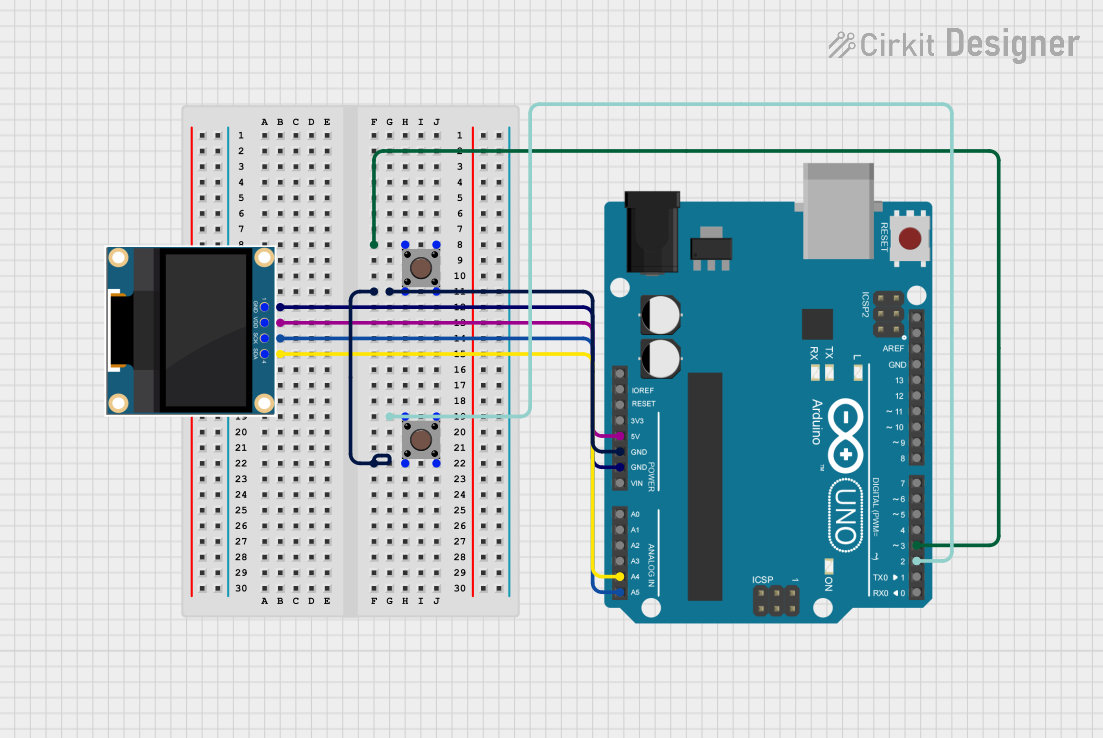
How to Use the Component in a Circuit
Connect the Pins:
- Connect the
VCCpin to the 3.3V or 5V power supply of your microcontroller. - Connect the
GNDpin to the ground of your circuit. - Connect the
SCLpin to the I2C clock pin of your microcontroller (e.g., A5 on Arduino UNO). - Connect the
SDApin to the I2C data pin of your microcontroller (e.g., A4 on Arduino UNO).
- Connect the
Install Required Libraries:
- For Arduino, install the
Adafruit_GFXandAdafruit_SSD1306libraries from the Arduino Library Manager.
- For Arduino, install the
Write and Upload Code:
- Use the example code below to display text or graphics on the OLED screen.
Example Code for Arduino UNO
#include <Wire.h>
#include <Adafruit_GFX.h>
#include <Adafruit_SSD1306.h>

// Define the OLED display width and height
#define SCREEN_WIDTH 128
#define SCREEN_HEIGHT 64

// Create an instance of the SSD1306 display object
Adafruit_SSD1306 display(SCREEN_WIDTH, SCREEN_HEIGHT, &Wire, -1);

void setup() {
  // Initialize serial communication for debugging
  Serial.begin(9600);

  // Initialize the OLED display
  if (!display.begin(SSD1306_I2C_ADDRESS, 0x3C)) {
    // If initialization fails, print an error message
    Serial.println(F("SSD1306 allocation failed"));
    for (;;); // Halt the program
  }

  // Clear the display buffer
  display.clearDisplay();

  // Set text size and color
  display.setTextSize(1); // Small text size
  display.setTextColor(SSD1306_WHITE);

  // Display a message
  display.setCursor(0, 0); // Set cursor to top-left corner
  display.println(F("Hello, OLED!"));
  display.display(); // Render the text on the screen
}

void loop() {
  // No actions in the loop for this example
}
Important Considerations and Best Practices
- Ensure the I2C address of the OLED display matches the address in your code. The default address is typically
0x3C. - Use pull-up resistors (4.7kΩ to 10kΩ) on the
SCLandSDAlines if your microcontroller does not have internal pull-ups. - Avoid exposing the display to direct sunlight for prolonged periods, as this may degrade the OLED material.
- Handle the module carefully to avoid damaging the fragile display surface.
Troubleshooting and FAQs
Common Issues and Solutions
The display does not turn on:
- Verify the power connections (
VCCandGND) and ensure the correct voltage is supplied. - Check the I2C connections (
SCLandSDA) and ensure they are properly connected to the microcontroller.
- Verify the power connections (
Nothing is displayed on the screen:
- Confirm that the I2C address in your code matches the display's address (default is
0x3C). - Ensure the required libraries (
Adafruit_GFXandAdafruit_SSD1306) are installed and up to date.
- Confirm that the I2C address in your code matches the display's address (default is
Flickering or unstable display:
- Check for loose connections in the circuit.
- Use shorter wires to reduce noise in the I2C communication.
Text or graphics appear distorted:
- Ensure the correct resolution (
128x64) is set in your code. - Clear the display buffer (
display.clearDisplay()) before rendering new content.
- Ensure the correct resolution (
FAQs
Q: Can I use this display with a 3.3V microcontroller?
A: Yes, the OLED display supports both 3.3V and 5V logic levels, making it compatible with a wide range of microcontrollers.
Q: How do I change the I2C address of the display?
A: Some OLED modules allow changing the I2C address by soldering jumpers on the back of the module. Refer to the module's datasheet for details.
Q: Can I display images on this OLED screen?
A: Yes, you can display images by converting them into a bitmap format and using the drawBitmap() function provided by the Adafruit_GFX library.
Q: What is the lifespan of the OLED display?
A: The typical lifespan of an OLED display is around 10,000 to 50,000 hours, depending on usage and brightness settings.