How to Use lidar: Examples, Pinouts, and Specs
Introduction
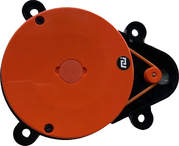
Lidar (Light Detection and Ranging) is a cutting-edge remote sensing technology that uses laser light to measure distances to objects. The Xiaomi Mi Lidar module is a compact and efficient device designed for applications requiring precise distance measurements and environmental mapping. It emits laser pulses and measures the time it takes for the light to return after reflecting off objects, enabling the creation of high-resolution maps and 3D models.
Explore Projects Built with lidar
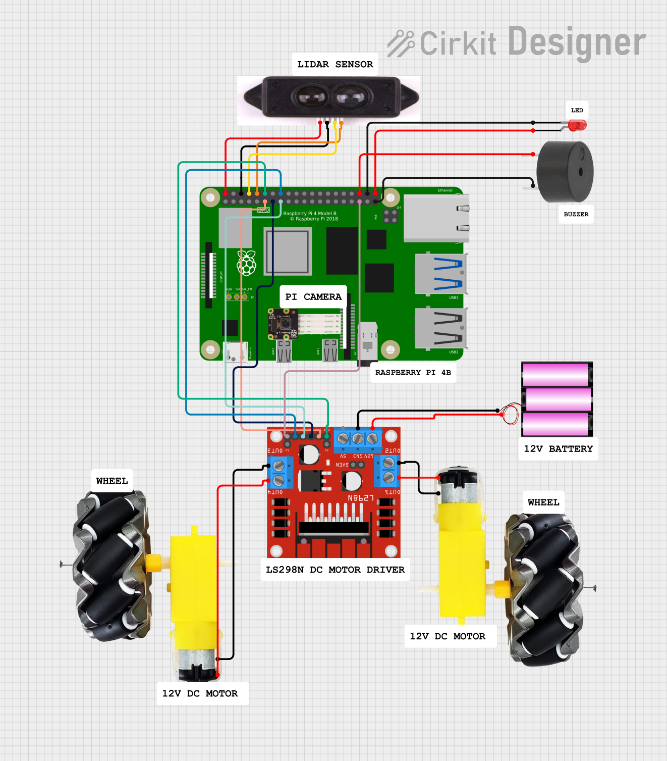
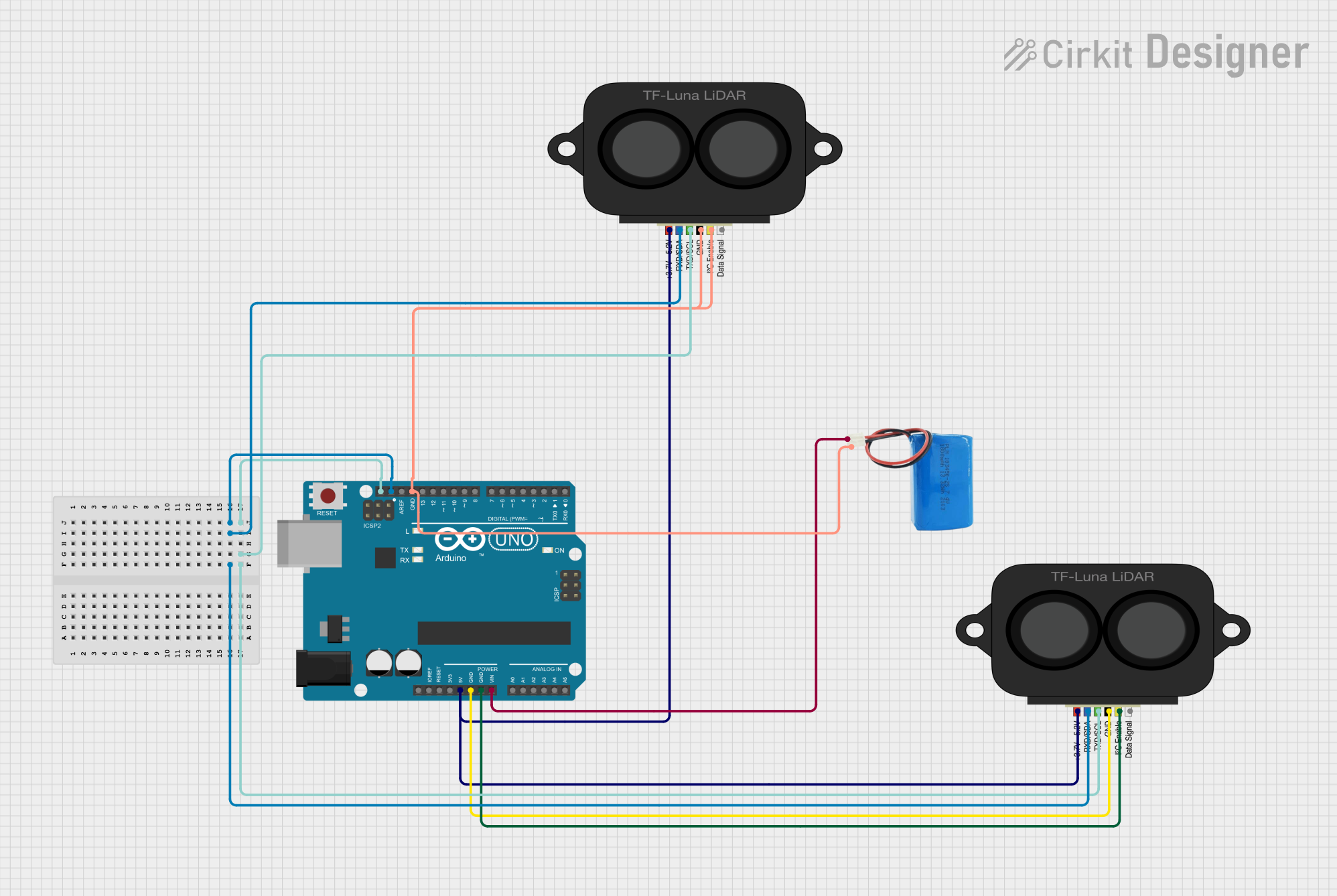
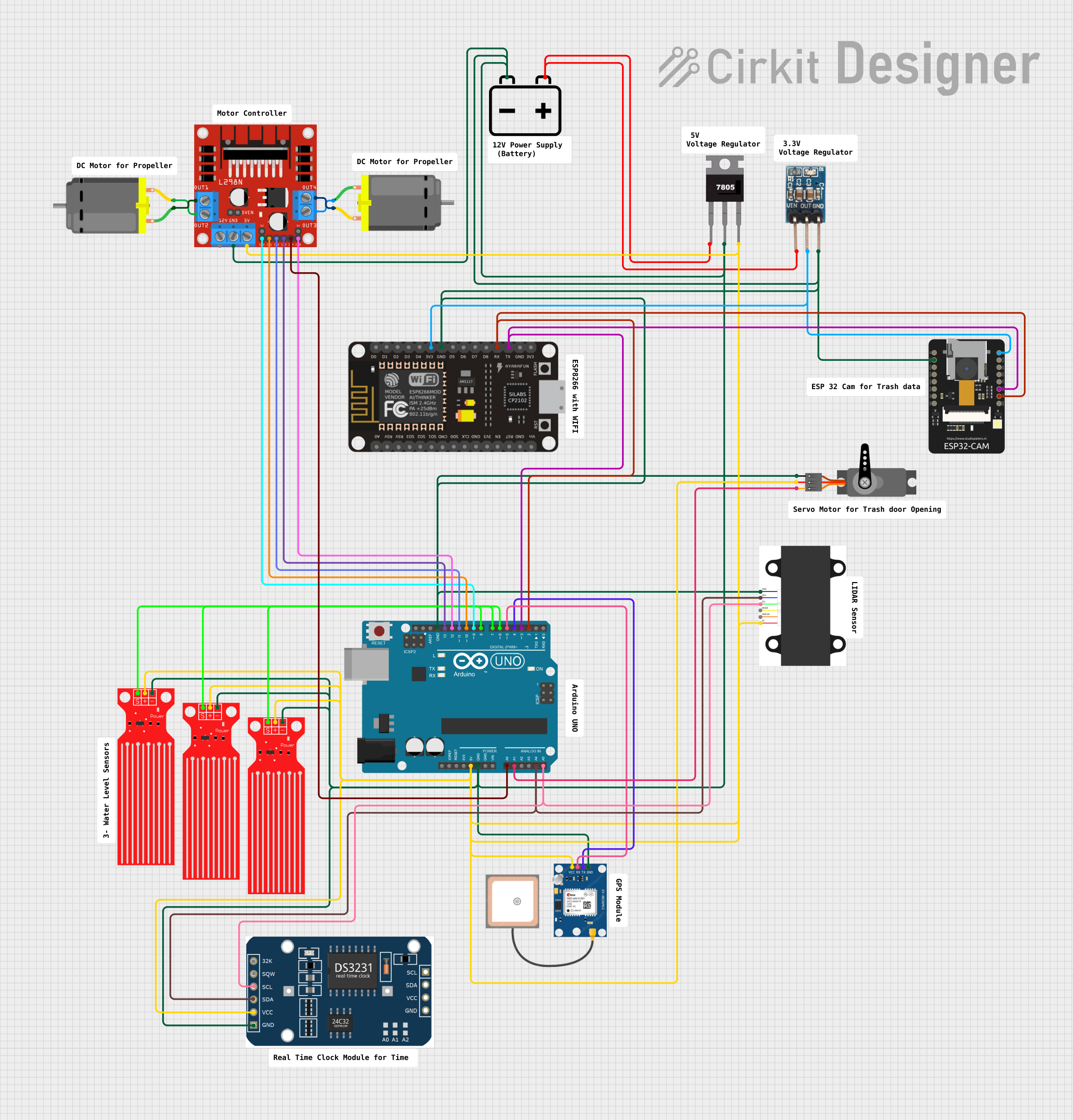

Explore Projects Built with lidar
Common Applications and Use Cases
- Autonomous vehicles and robotics for navigation and obstacle detection
- Smart home devices, such as robotic vacuum cleaners
- Industrial automation and object tracking
- Environmental monitoring and 3D terrain mapping
- Augmented reality (AR) and virtual reality (VR) systems
Technical Specifications
The Xiaomi Mi Lidar module is designed for high performance and reliability. Below are its key technical details:
Key Technical Details
| Parameter | Specification |
|---|---|
| Operating Voltage | 5V DC |
| Power Consumption | ≤ 3W |
| Measurement Range | 0.1m to 8m |
| Accuracy | ±2% |
| Scanning Frequency | 5 Hz to 12 Hz |
| Laser Wavelength | 905 nm |
| Communication Interface | UART (3.3V logic level) |
| Dimensions | 75mm x 75mm x 40mm |
| Weight | 200g |
Pin Configuration and Descriptions
The Xiaomi Mi Lidar module typically features a 4-pin connector for power and communication. Below is the pinout:
| Pin Number | Name | Description |
|---|---|---|
| 1 | VCC | Power input (5V DC) |
| 2 | GND | Ground |
| 3 | TX | UART Transmit (3.3V logic level) |
| 4 | RX | UART Receive (3.3V logic level) |
Usage Instructions
How to Use the Xiaomi Mi Lidar in a Circuit
- Power Supply: Connect the
VCCpin to a 5V DC power source and theGNDpin to ground. - Communication: Use the
TXandRXpins to interface with a microcontroller or computer via UART. Ensure the logic level is 3.3V to avoid damaging the module. - Mounting: Secure the Lidar module on a stable platform to minimize vibrations during operation.
- Data Processing: Use the UART interface to receive distance and angle data from the Lidar. The data can be processed to create maps or detect obstacles.
Important Considerations and Best Practices
- Laser Safety: The Xiaomi Mi Lidar uses a Class 1 laser, which is safe under normal operating conditions. Avoid direct eye exposure to the laser beam.
- Environmental Conditions: Ensure the module is used in environments free from excessive dust, smoke, or reflective surfaces, as these can affect accuracy.
- Power Supply Stability: Use a stable 5V power source to prevent fluctuations that could impact performance.
- UART Configuration: Set the UART baud rate to the default value specified in the module's datasheet (typically 115200 bps).
Example: Connecting Xiaomi Mi Lidar to Arduino UNO
Below is an example of how to connect and use the Xiaomi Mi Lidar with an Arduino UNO:
Wiring Diagram
| Lidar Pin | Arduino Pin |
|---|---|
| VCC | 5V |
| GND | GND |
| TX | RX (Pin 0) |
| RX | TX (Pin 1) |
Arduino Code
// Example code to read data from Xiaomi Mi Lidar using Arduino UNO
// Ensure the Lidar is connected to the correct pins as per the wiring diagram

#include <SoftwareSerial.h>

// Define RX and TX pins for SoftwareSerial
SoftwareSerial lidarSerial(10, 11); // RX = Pin 10, TX = Pin 11

void setup() {
  Serial.begin(9600); // Initialize Serial Monitor
  lidarSerial.begin(115200); // Initialize Lidar UART communication

  Serial.println("Xiaomi Mi Lidar Initialized");
}

void loop() {
  // Check if data is available from the Lidar
  if (lidarSerial.available()) {
    String lidarData = ""; // Variable to store incoming data

    // Read all available data from the Lidar
    while (lidarSerial.available()) {
      char c = lidarSerial.read();
      lidarData += c;
    }

    // Print the received data to the Serial Monitor
    Serial.println("Lidar Data: " + lidarData);
  }

  delay(100); // Small delay to avoid flooding the Serial Monitor
}
Troubleshooting and FAQs
Common Issues and Solutions
No Data Received from Lidar
- Cause: Incorrect UART connection or baud rate mismatch.
- Solution: Verify the TX and RX connections. Ensure the baud rate is set to 115200 bps.
Inaccurate Distance Measurements
- Cause: Reflective or transparent surfaces in the environment.
- Solution: Avoid using the Lidar near mirrors, glass, or highly reflective objects.
Lidar Module Not Powering On
- Cause: Insufficient power supply or loose connections.
- Solution: Ensure the power source provides a stable 5V and check all connections.
Interference from Ambient Light
- Cause: Strong sunlight or other light sources interfering with the laser.
- Solution: Use the Lidar in controlled lighting conditions or shield it from direct sunlight.
FAQs
Q1: Can the Xiaomi Mi Lidar detect transparent objects?
A1: No, the Lidar may struggle to detect transparent or highly reflective objects due to the nature of laser light reflection.
Q2: What is the maximum range of the Xiaomi Mi Lidar?
A2: The maximum range is 8 meters under optimal conditions.
Q3: Can I use the Xiaomi Mi Lidar outdoors?
A3: Yes, but ensure it is protected from excessive dust, rain, and direct sunlight for accurate performance.
Q4: Is the Xiaomi Mi Lidar compatible with Raspberry Pi?
A4: Yes, the Lidar can be interfaced with Raspberry Pi using the UART interface.