
How to Use Quad bit comparator: Examples, Pinouts, and Specs
 Design with Quad bit comparator in Cirkit Designer
Introduction
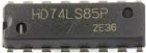
The 74LS85 is a quad 4-bit magnitude comparator manufactured by Texas Instruments (TI). It is designed to compare two 4-bit binary numbers and determine their relative magnitudes. The component provides three outputs indicating whether one number is greater than, less than, or equal to the other. This makes it an essential component in digital systems for decision-making, sorting, and control applications.
Explore Projects Built with Quad bit comparator
 Open Project in Cirkit Designer
 Open Project in Cirkit Designer
 Open Project in Cirkit Designer
 Open Project in Cirkit Designer
Explore Projects Built with Quad bit comparator
Open Project in Cirkit DesignerOpen Project in Cirkit DesignerOpen Project in Cirkit DesignerOpen Project in Cirkit DesignerCommon Applications
- Digital sorting and ranking systems
- Arithmetic and logic units (ALUs)
- Data comparison in microprocessors
- Priority encoders
- Control systems for decision-making
Technical Specifications
Key Technical Details
| Parameter | Value |
|---|---|
| Supply Voltage (Vcc) | 4.75V to 5.25V |
| Input Voltage (VI) | 0V to 5.5V |
| High-Level Output Voltage (VOH) | 2.7V (min) at 4mA load |
| Low-Level Output Voltage (VOL) | 0.4V (max) at 4mA load |
| Propagation Delay | 18ns (typical) |
| Power Dissipation | 20mW (typical) |
| Operating Temperature | 0°C to 70°C |
| Package Types | DIP-16, SOIC-16 |
Pin Configuration and Descriptions
The 74LS85 is a 16-pin IC. Below is the pinout and description:
| Pin No. | Pin Name | Description |
|---|---|---|
| 1 | A3 | Most significant bit (MSB) of 4-bit input A |
| 2 | B3 | Most significant bit (MSB) of 4-bit input B |
| 3 | A2 | Second most significant bit of 4-bit input A |
| 4 | B2 | Second most significant bit of 4-bit input B |
| 5 | A1 | Second least significant bit of 4-bit input A |
| 6 | B1 | Second least significant bit of 4-bit input B |
| 7 | A0 | Least significant bit (LSB) of 4-bit input A |
| 8 | GND | Ground (0V) |
| 9 | B0 | Least significant bit (LSB) of 4-bit input B |
| 10 | I(A<B) | Cascading input: A is less than B |
| 11 | I(A=B) | Cascading input: A is equal to B |
| 12 | I(A>B) | Cascading input: A is greater than B |
| 13 | O(A<B) | Output: A is less than B |
| 14 | O(A=B) | Output: A is equal to B |
| 15 | O(A>B) | Output: A is greater than B |
| 16 | Vcc | Positive supply voltage (typically +5V) |
Usage Instructions
How to Use the 74LS85 in a Circuit
- Power Supply: Connect pin 16 to a +5V power supply and pin 8 to ground.
- Inputs: Provide the two 4-bit binary numbers to be compared on pins A3–A0 and B3–B0.
- A3 is the MSB of input A, and A0 is the LSB.
- B3 is the MSB of input B, and B0 is the LSB.
- Cascading Inputs: If cascading multiple 74LS85 ICs for comparing larger numbers, connect the cascading inputs (pins 10, 11, and 12) to the outputs of the previous stage.
- Outputs: Read the comparison results from pins 13, 14, and 15:
- Pin 13 (O(A<B)): High if A < B.
- Pin 14 (O(A=B)): High if A = B.
- Pin 15 (O(A>B)): High if A > B.
Important Considerations
- Ensure the supply voltage is within the recommended range (4.75V to 5.25V).
- Use pull-up resistors on the outputs if required by your circuit design.
- Avoid leaving unused inputs floating; connect them to ground or Vcc as needed.
- For cascading, ensure proper timing and synchronization between stages.
Example: Connecting the 74LS85 to an Arduino UNO
The 74LS85 can be interfaced with an Arduino UNO to compare two 4-bit binary numbers. Below is an example code snippet:
// Define input pins for binary numbers A and B
const int A_pins[4] = {2, 3, 4, 5}; // A0 to A3 connected to Arduino pins 2-5
const int B_pins[4] = {6, 7, 8, 9}; // B0 to B3 connected to Arduino pins 6-9

// Define output pins for comparison results
const int O_A_less_B = 10; // O(A<B) connected to Arduino pin 10
const int O_A_equal_B = 11; // O(A=B) connected to Arduino pin 11
const int O_A_greater_B = 12; // O(A>B) connected to Arduino pin 12

void setup() {
  // Set A and B pins as outputs
  for (int i = 0; i < 4; i++) {
    pinMode(A_pins[i], OUTPUT);
    pinMode(B_pins[i], OUTPUT);
  }

  // Set output pins as inputs
  pinMode(O_A_less_B, INPUT);
  pinMode(O_A_equal_B, INPUT);
  pinMode(O_A_greater_B, INPUT);

  Serial.begin(9600); // Initialize serial communication
}

void loop() {
  // Example: Set binary numbers A = 5 (0101) and B = 3 (0011)
  int A[4] = {1, 0, 1, 0}; // Binary 0101
  int B[4] = {1, 1, 0, 0}; // Binary 0011

  // Write A and B values to the 74LS85
  for (int i = 0; i < 4; i++) {
    digitalWrite(A_pins[i], A[i]);
    digitalWrite(B_pins[i], B[i]);
  }

  // Read comparison results
  bool less = digitalRead(O_A_less_B);
  bool equal = digitalRead(O_A_equal_B);
  bool greater = digitalRead(O_A_greater_B);

  // Print results to the serial monitor
  Serial.print("A < B: "); Serial.println(less);
  Serial.print("A = B: "); Serial.println(equal);
  Serial.print("A > B: "); Serial.println(greater);

  delay(1000); // Wait for 1 second before repeating
}
Notes:
- Ensure proper connections between the Arduino and the 74LS85.
- Use current-limiting resistors if necessary to protect the Arduino pins.
Troubleshooting and FAQs
Common Issues
Incorrect Output Values:
- Cause: Floating inputs or incorrect wiring.
- Solution: Verify all connections and ensure unused inputs are tied to ground or Vcc.
No Output Signal:
- Cause: Missing or incorrect power supply.
- Solution: Check the Vcc and GND connections and ensure the supply voltage is within the specified range.
Erratic Behavior:
- Cause: Noise or unstable power supply.
- Solution: Use decoupling capacitors (e.g., 0.1µF) near the Vcc pin to stabilize the power supply.
FAQs
Q1: Can the 74LS85 compare numbers larger than 4 bits?
A1: Yes, by cascading multiple 74LS85 ICs, you can compare numbers of any size. Use the cascading inputs and outputs for this purpose.
Q2: What happens if both inputs are left floating?
A2: Floating inputs can cause unpredictable behavior. Always tie unused inputs to ground or Vcc.
Q3: Can the 74LS85 operate at 3.3V?
A3: No, the 74LS85 is designed for a 5V supply. Operating it at 3.3V may result in unreliable performance.
Q4: Is the 74LS85 compatible with CMOS logic?
A4: The 74LS85 is a TTL device. While it can interface with CMOS logic, ensure proper voltage levels and consider using level shifters if necessary.