Cirkit Designer Logo
Cirkit Designer
Your all-in-one circuit design IDE
Home / 
Component Documentation

How to Use POWER SUPPLY 5V 5AMP: Examples, Pinouts, and Specs

Image of POWER SUPPLY 5V 5AMP
Cirkit Designer LogoDesign with POWER SUPPLY 5V 5AMP in Cirkit Designer

Introduction

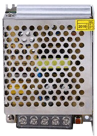
The POWER SUPPLY 5V 5AMP is a reliable and efficient device designed to convert electrical energy into a stable 5-volt DC output with a maximum current capacity of 5 amps. This power supply is widely used in powering electronic devices, microcontrollers, sensors, and other circuits that require a steady 5V power source. Its robust design ensures consistent performance, making it ideal for both hobbyist and professional applications.

Explore Projects Built with POWER SUPPLY 5V 5AMP

Use Cirkit Designer to design, explore, and prototype these projects online. Some projects support real-time simulation. Click "Open Project" to start designing instantly!
Dual 5V Power Supply Distribution Circuit with Toggle Switch Control
Image of rfdriver: A project utilizing POWER SUPPLY 5V 5AMP in a practical application
This circuit consists of two 5V 5A power supplies connected to an AC wall plug point, providing DC output through a 12-way connector. The ground connections from both power supplies are interconnected and also connected to the ground pins of two toggle switches. The DC outputs from the power supplies are separately connected to different pins on the 12-way connector, with each power supply output being switchable via one of the toggle switches.
Cirkit Designer LogoOpen Project in Cirkit Designer
12V to 5V Power Supply with LED Indicator and Push Switch
Image of Power Supply LVCO: A project utilizing POWER SUPPLY 5V 5AMP in a practical application
This circuit is a 12V to 5V regulated power supply with an LED indicator. It uses a 5408 diode for reverse polarity protection, an LM340T5 7805 voltage regulator to step down the voltage to 5V, and a push switch to control the LED indicator. The circuit also includes capacitors for filtering and a resistor to limit the current through the LED.
Cirkit Designer LogoOpen Project in Cirkit Designer
12V UPS System with Dual 18650 Li-ion Battery Backup and Voltage Regulation
Image of Power supply: A project utilizing POWER SUPPLY 5V 5AMP in a practical application
This circuit is designed to provide an uninterruptible power supply (UPS) system with a 12V DC output. It includes a 12V 5A power supply connected to an AC source through a toggle switch, which charges a pair of 18650 Li-ion batteries via a voltage regulator (XL4016). The UPS module ensures a continuous power supply to the load by switching between the power supply and the battery bank.
Cirkit Designer LogoOpen Project in Cirkit Designer
Battery-Powered USB Charger with LED Indicator and DC Motor
Image of Copy of Hand Crank mobile charger : A project utilizing POWER SUPPLY 5V 5AMP in a practical application
This circuit converts AC power to DC using a bridge rectifier and regulates the voltage to 5V with a 7805 voltage regulator. It powers a USB port and indicates power status with an LED, while also providing a charging interface through a multi-charging cable.
Cirkit Designer LogoOpen Project in Cirkit Designer

Explore Projects Built with POWER SUPPLY 5V 5AMP

Use Cirkit Designer to design, explore, and prototype these projects online. Some projects support real-time simulation. Click "Open Project" to start designing instantly!
Image of rfdriver: A project utilizing POWER SUPPLY 5V 5AMP in a practical application
Dual 5V Power Supply Distribution Circuit with Toggle Switch Control
This circuit consists of two 5V 5A power supplies connected to an AC wall plug point, providing DC output through a 12-way connector. The ground connections from both power supplies are interconnected and also connected to the ground pins of two toggle switches. The DC outputs from the power supplies are separately connected to different pins on the 12-way connector, with each power supply output being switchable via one of the toggle switches.
Cirkit Designer LogoOpen Project in Cirkit Designer
Image of Power Supply LVCO: A project utilizing POWER SUPPLY 5V 5AMP in a practical application
12V to 5V Power Supply with LED Indicator and Push Switch
This circuit is a 12V to 5V regulated power supply with an LED indicator. It uses a 5408 diode for reverse polarity protection, an LM340T5 7805 voltage regulator to step down the voltage to 5V, and a push switch to control the LED indicator. The circuit also includes capacitors for filtering and a resistor to limit the current through the LED.
Cirkit Designer LogoOpen Project in Cirkit Designer
Image of Power supply: A project utilizing POWER SUPPLY 5V 5AMP in a practical application
12V UPS System with Dual 18650 Li-ion Battery Backup and Voltage Regulation
This circuit is designed to provide an uninterruptible power supply (UPS) system with a 12V DC output. It includes a 12V 5A power supply connected to an AC source through a toggle switch, which charges a pair of 18650 Li-ion batteries via a voltage regulator (XL4016). The UPS module ensures a continuous power supply to the load by switching between the power supply and the battery bank.
Cirkit Designer LogoOpen Project in Cirkit Designer
Image of Copy of Hand Crank mobile charger : A project utilizing POWER SUPPLY 5V 5AMP in a practical application
Battery-Powered USB Charger with LED Indicator and DC Motor
This circuit converts AC power to DC using a bridge rectifier and regulates the voltage to 5V with a 7805 voltage regulator. It powers a USB port and indicates power status with an LED, while also providing a charging interface through a multi-charging cable.
Cirkit Designer LogoOpen Project in Cirkit Designer

Common Applications and Use Cases

  • Powering microcontroller boards (e.g., Arduino, Raspberry Pi)
  • Driving LED strips and lighting systems
  • Supplying power to sensors and actuators
  • Charging USB devices
  • Providing power for small motors and robotics projects

Technical Specifications

The following table outlines the key technical details of the POWER SUPPLY 5V 5AMP:

Parameter Specification
Input Voltage Range 100-240V AC, 50/60Hz
Output Voltage 5V DC
Maximum Output Current 5A
Power Output 25W
Efficiency ≥85%
Ripple and Noise ≤50mV
Operating Temperature -10°C to +50°C
Protection Features Overload, Overvoltage, Short Circuit

Pin Configuration and Descriptions

The POWER SUPPLY 5V 5AMP typically has the following input and output connections:

Pin/Terminal Description
AC-L (Line) Live wire for AC input
AC-N (Neutral) Neutral wire for AC input
GND Ground connection for DC output
+5V Positive 5V DC output terminal

Usage Instructions

How to Use the Component in a Circuit

  1. Connect the Input:

    • Ensure the power supply is disconnected from the mains before wiring.
    • Connect the AC-L (Line) and AC-N (Neutral) terminals to the corresponding live and neutral wires of the AC mains supply.
    • Double-check the connections to avoid incorrect wiring.
  2. Connect the Output:

    • Use the +5V terminal for the positive DC output and the GND terminal for the ground connection.
    • Ensure the load connected to the power supply does not exceed the maximum current rating of 5A.
  3. Power On:

    • After verifying all connections, plug the power supply into the mains and switch it on.
    • Measure the output voltage with a multimeter to confirm a stable 5V output before connecting sensitive devices.

Important Considerations and Best Practices

  • Load Capacity: Do not exceed the 5A current limit to prevent overheating or damage.
  • Ventilation: Ensure proper airflow around the power supply to avoid overheating.
  • Polarity: Always check the polarity of the output connections to prevent damage to connected devices.
  • Safety: Avoid touching the terminals while the power supply is connected to the mains.

Example: Using with an Arduino UNO

The POWER SUPPLY 5V 5AMP can be used to power an Arduino UNO via its 5V pin. Below is an example of how to connect and use it:

  1. Connect the +5V terminal of the power supply to the 5V pin on the Arduino UNO.
  2. Connect the GND terminal of the power supply to the GND pin on the Arduino UNO.
  3. Ensure the Arduino is not connected to USB power simultaneously to avoid conflicts.

Here is a simple Arduino sketch to blink an LED while powered by the power supply:

// This sketch blinks an LED connected to pin 13 of the Arduino UNO.
// Ensure the Arduino is powered by the 5V 5A power supply.

void setup() {
  pinMode(13, OUTPUT); // Set pin 13 as an output pin
}

void loop() {
  digitalWrite(13, HIGH); // Turn the LED on
  delay(1000);            // Wait for 1 second
  digitalWrite(13, LOW);  // Turn the LED off
  delay(1000);            // Wait for 1 second
}

Troubleshooting and FAQs

Common Issues and Solutions

  1. No Output Voltage:

    • Cause: Incorrect wiring or no AC input.
    • Solution: Verify the AC input connections and ensure the mains power is on.
  2. Output Voltage Fluctuates:

    • Cause: Overloading or insufficient ventilation.
    • Solution: Reduce the load to within the 5A limit and ensure proper airflow.
  3. Power Supply Overheats:

    • Cause: Continuous operation at maximum load or poor ventilation.
    • Solution: Operate below the maximum load for extended periods and improve ventilation.
  4. Device Not Powering On:

    • Cause: Incorrect polarity or loose connections.
    • Solution: Double-check the polarity and ensure all connections are secure.

FAQs

Q: Can I use this power supply to charge USB devices?
A: Yes, but you will need a USB breakout board or adapter to connect the 5V output to the USB device.

Q: Is this power supply suitable for outdoor use?
A: No, this power supply is not weatherproof. Use it in a dry, indoor environment.

Q: Can I connect multiple devices to this power supply?
A: Yes, as long as the total current draw does not exceed 5A.

Q: What happens if I exceed the 5A limit?
A: The power supply's overload protection will activate, shutting down the output to prevent damage.

This concludes the documentation for the POWER SUPPLY 5V 5AMP.