How to Use 5V Relay Module: Examples, Pinouts, and Specs
Introduction
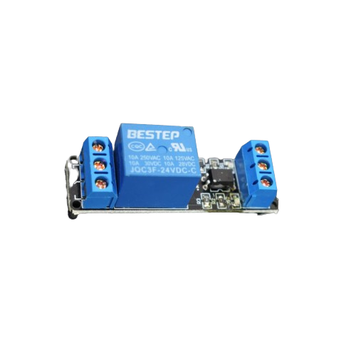
A 5V Relay Module is an electronic switch that allows a low voltage control signal to switch a higher voltage circuit on or off. It typically consists of a relay, which is an electromechanical switch, and additional components such as transistors, diodes, and optocouplers to interface with microcontrollers or other control systems.
Explore Projects Built with 5V Relay Module


Explore Projects Built with 5V Relay Module
Common Applications and Use Cases
- Home automation systems (e.g., controlling lights, fans, or appliances)
- Industrial control systems
- Robotics and IoT projects
- Motor control
- Switching high-power devices using microcontrollers like Arduino, Raspberry Pi, or ESP32
Technical Specifications
Below are the key technical details of a standard 5V Relay Module:
| Parameter | Specification |
|---|---|
| Operating Voltage | 5V DC |
| Trigger Voltage | 3.3V to 5V DC |
| Maximum Load Voltage | 250V AC / 30V DC |
| Maximum Load Current | 10A |
| Relay Type | SPDT (Single Pole Double Throw) |
| Isolation | Optocoupler-based isolation |
| Dimensions | Typically 50mm x 26mm x 18mm |
| Indicator LED | Yes (indicates relay activation) |
| Control Signal Logic | Active LOW (relay activates when input pin |
| is pulled LOW) |
Pin Configuration and Descriptions
The 5V Relay Module typically has the following pins:
| Pin Name | Description |
|---|---|
| VCC | Connect to 5V DC power supply. |
| GND | Connect to ground of the power supply. |
| IN | Control signal input. A LOW signal activates the relay, and a HIGH signal |
| deactivates it. |
The relay also has three terminal blocks for connecting the load:
| Terminal | Description |
|---|---|
| COM | Common terminal. Connect to one side of the load or power source. |
| NO | Normally Open terminal. The circuit is open when the relay is inactive and |
| closes when the relay is activated. | |
| NC | Normally Closed terminal. The circuit is closed when the relay is inactive and |
| opens when the relay is activated. |
Usage Instructions
How to Use the 5V Relay Module in a Circuit
- Power the Module: Connect the VCC pin to a 5V DC power supply and the GND pin to ground.
- Connect the Control Signal: Connect the IN pin to a digital output pin of a microcontroller (e.g., Arduino).
- Connect the Load:
- Identify whether you want the load to be connected to the Normally Open (NO) or Normally Closed (NC) terminal.
- Connect one side of the load to the COM terminal and the other side to the NO or NC terminal, depending on your application.
- Ensure the load voltage and current do not exceed the relay's maximum ratings.
- Control the Relay: Use the microcontroller to send a LOW signal to the IN pin to activate the relay and switch the load.
Important Considerations and Best Practices
- Isolation: Ensure proper electrical isolation between the low voltage control circuit and the high voltage load circuit.
- Flyback Diode: The module typically includes a flyback diode to protect the relay coil from voltage spikes. Verify this feature in your module.
- Power Supply: Use a stable 5V power supply to avoid erratic relay behavior.
- Inductive Loads: For inductive loads (e.g., motors), consider adding a snubber circuit to protect the relay contacts from arcing.
- Avoid Overloading: Do not exceed the relay's maximum voltage and current ratings to prevent damage.
Example: Using the 5V Relay Module with Arduino UNO
Below is an example of how to control a 5V Relay Module using an Arduino UNO:
// Define the pin connected to the relay module
const int relayPin = 7;

void setup() {
  // Set the relay pin as an output
  pinMode(relayPin, OUTPUT);

  // Ensure the relay is off initially
  digitalWrite(relayPin, HIGH); // Relay is active LOW
}

void loop() {
  // Turn the relay ON
  digitalWrite(relayPin, LOW); // Activate the relay
  delay(5000); // Keep the relay ON for 5 seconds

  // Turn the relay OFF
  digitalWrite(relayPin, HIGH); // Deactivate the relay
  delay(5000); // Keep the relay OFF for 5 seconds
}
Notes:
- The relay is active LOW, meaning it activates when the control signal is LOW.
- Ensure the load connected to the relay is within its rated voltage and current limits.
Troubleshooting and FAQs
Common Issues and Solutions
Relay Not Activating:
- Cause: Insufficient voltage or current to the relay module.
- Solution: Verify that the VCC pin is receiving a stable 5V supply and the IN pin is receiving the correct control signal.
Erratic Behavior:
- Cause: Noise or unstable power supply.
- Solution: Use a decoupling capacitor (e.g., 100µF) across the VCC and GND pins to stabilize the power supply.
Load Not Switching:
- Cause: Incorrect wiring of the load to the relay terminals.
- Solution: Double-check the connections to the COM, NO, and NC terminals.
Relay Stuck in One State:
- Cause: Relay contacts may be damaged due to overloading.
- Solution: Replace the relay module and ensure the load does not exceed the relay's ratings.
FAQs
Q1: Can I use the 5V Relay Module with a 3.3V microcontroller?
A1: Yes, most 5V Relay Modules can be triggered with a 3.3V control signal. However, verify the module's trigger voltage range in its datasheet.
Q2: Is it safe to use the relay for AC loads?
A2: Yes, the relay can handle AC loads up to 250V, but ensure proper insulation and safety precautions when working with high voltages.
Q3: Can I control multiple relays with one microcontroller?
A3: Yes, you can control multiple relays, but ensure the microcontroller has enough GPIO pins and the power supply can handle the combined current draw.
Q4: Why is the relay clicking but not switching the load?
A4: This could be due to incorrect wiring or a faulty load. Verify the connections and test the load separately.
By following this documentation, you can effectively use the 5V Relay Module in your projects while ensuring safety and reliability.