How to Use Stereo FM module: Examples, Pinouts, and Specs
Introduction
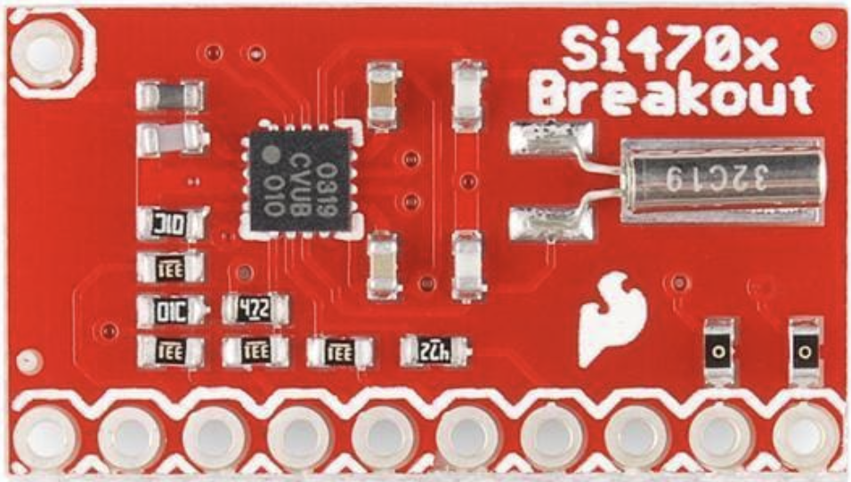
The Stereo FM Module (Si470x Breakout) by SparkFun is a compact and versatile device designed to receive and decode FM radio signals, providing high-quality stereo audio output. This module integrates advanced features such as automatic frequency control, stereo decoding, and programmable settings, making it ideal for a wide range of applications.
Explore Projects Built with Stereo FM module
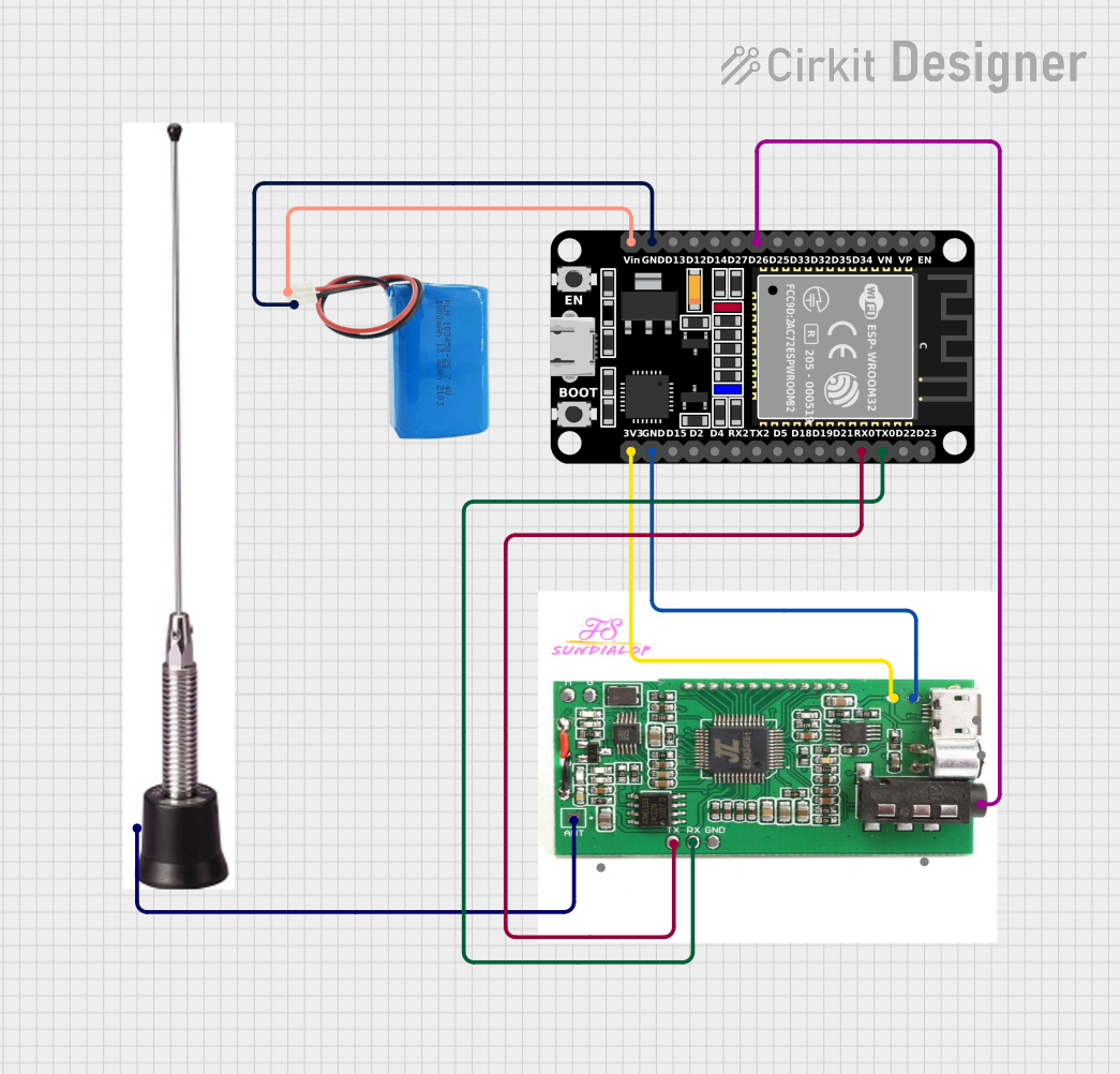

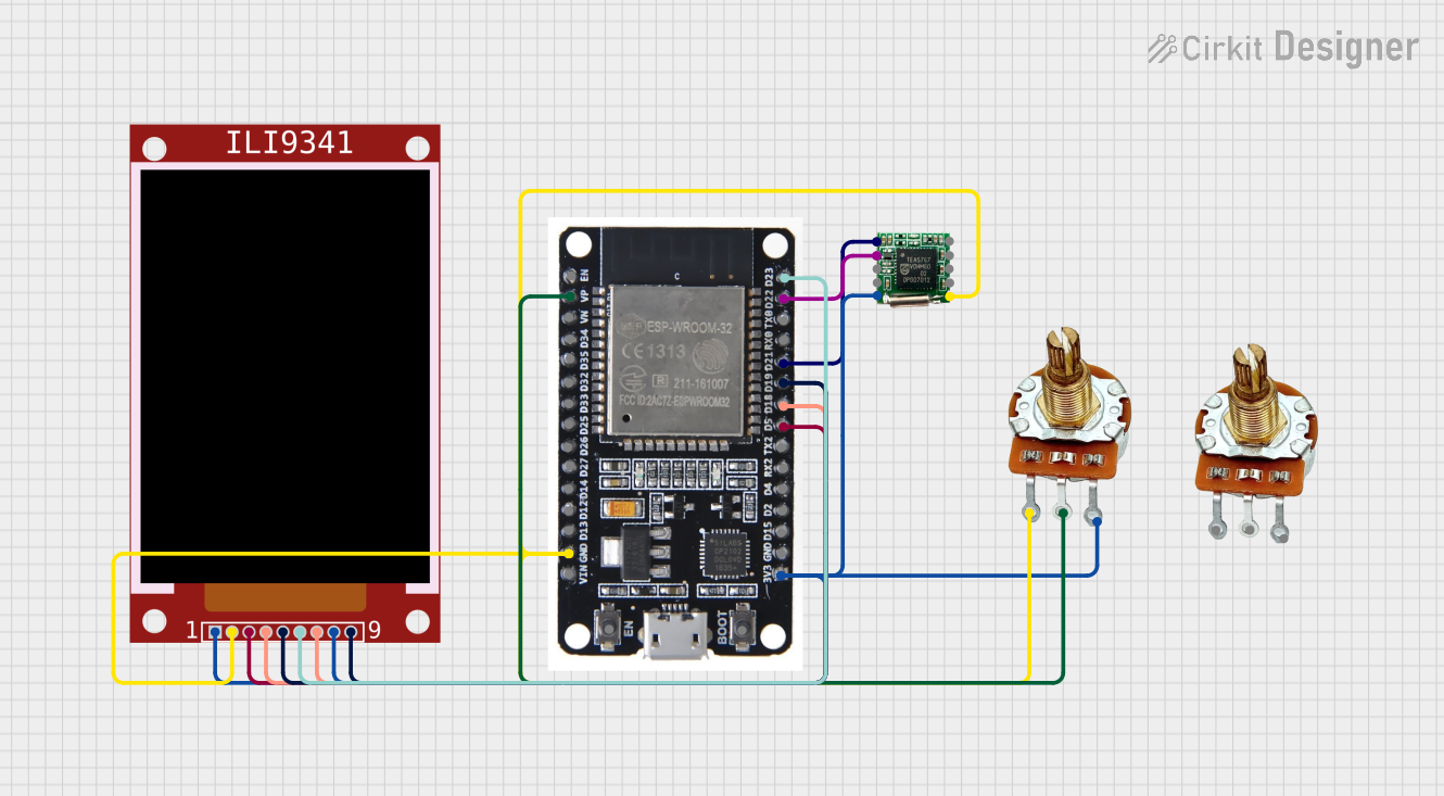
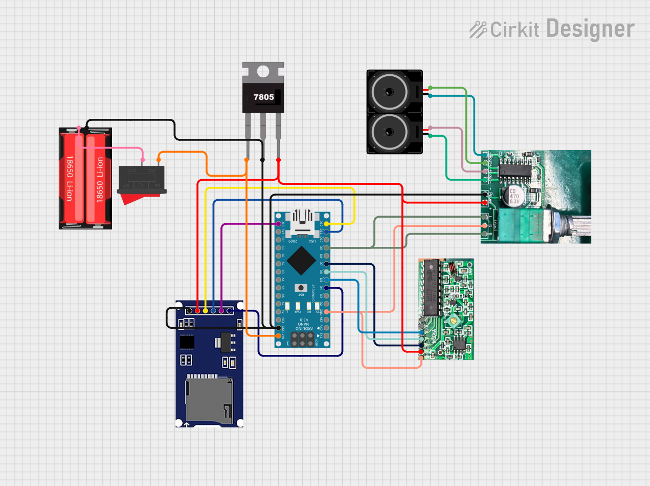
Explore Projects Built with Stereo FM module
Common Applications and Use Cases
- FM radio receivers for DIY electronics projects
- Portable audio systems
- Embedded systems requiring FM radio functionality
- Educational projects for learning about RF communication
- Internet of Things (IoT) devices with audio capabilities
Technical Specifications
The following table outlines the key technical details of the Si470x Breakout module:
| Parameter | Value |
|---|---|
| Operating Voltage | 2.7V to 5.5V |
| Operating Current | ~20 mA |
| Frequency Range | 76 MHz to 108 MHz |
| Audio Output | Stereo (Left and Right channels) |
| Communication Interface | I²C |
| Sensitivity | -110 dBm |
| Dimensions | 0.8" x 0.8" (20.3mm x 20.3mm) |
Pin Configuration and Descriptions
The Si470x Breakout module has the following pin layout:
| Pin | Name | Description |
|---|---|---|
| 1 | GND | Ground connection |
| 2 | 3.3V | Power supply input (3.3V recommended) |
| 3 | SDA | I²C data line for communication |
| 4 | SCL | I²C clock line for communication |
| 5 | RST | Reset pin (active low) |
| 6 | GPO1 | General-purpose output 1 (configurable) |
| 7 | GPO2 | General-purpose output 2 (configurable) |
| 8 | ANT | Antenna input for receiving FM signals |
| 9 | LOUT | Left audio output |
| 10 | ROUT | Right audio output |
Usage Instructions
How to Use the Component in a Circuit
- Power Supply: Connect the
3.3Vpin to a regulated 3.3V power source and theGNDpin to ground. - Antenna: Attach an external antenna to the
ANTpin for optimal FM signal reception. A simple wire of ~75 cm can work as an antenna. - Audio Output: Connect the
LOUTandROUTpins to an audio amplifier or headphones for stereo audio output. - I²C Communication: Use the
SDAandSCLpins to interface with a microcontroller (e.g., Arduino) for controlling the module. - Reset: Connect the
RSTpin to the microcontroller or a pull-up resistor to ensure proper initialization.
Important Considerations and Best Practices
- Use a decoupling capacitor (e.g., 0.1 µF) near the power supply pins to reduce noise.
- Ensure the antenna is properly positioned to maximize signal reception.
- Avoid placing the module near high-frequency noise sources, such as switching power supplies.
- Use pull-up resistors (typically 4.7 kΩ) on the
SDAandSCLlines for reliable I²C communication.
Example: Connecting to an Arduino UNO
Below is an example of how to use the Si470x Breakout module with an Arduino UNO to tune into an FM station:
Circuit Connections
3.3V→ Arduino3.3VGND→ ArduinoGNDSDA→ ArduinoA4SCL→ ArduinoA5RST→ Arduino digital pin2ANT→ External antenna (e.g., 75 cm wire)LOUTandROUT→ Audio amplifier or headphones
Arduino Code
#include <Wire.h>
#include <Si4703_Breakout.h> // Include the Si4703 library

#define RESET_PIN 2 // Define the reset pin

Si4703_Breakout radio; // Create an instance of the Si4703 class

void setup() {
  pinMode(RESET_PIN, OUTPUT); // Set the reset pin as output
  digitalWrite(RESET_PIN, LOW); // Hold the reset pin low
  delay(1); // Wait for 1 ms
  digitalWrite(RESET_PIN, HIGH); // Release the reset pin

  Wire.begin(); // Initialize I²C communication
  if (!radio.begin()) {
    // If initialization fails, print an error message
    Serial.println("Radio initialization failed!");
    while (1); // Halt the program
  }

  radio.setFrequency(101.1); // Set the FM frequency to 101.1 MHz
  Serial.begin(9600); // Start serial communication for debugging
  Serial.println("Radio initialized and tuned to 101.1 MHz");
}

void loop() {
  // The main loop can be used to adjust frequency or volume
}
Troubleshooting and FAQs
Common Issues and Solutions
No Audio Output:
- Ensure the
LOUTandROUTpins are connected to an audio amplifier or headphones. - Verify that the module is powered correctly and the antenna is connected.
- Ensure the
Poor Signal Reception:
- Check the antenna connection and ensure it is properly positioned.
- Move the module away from sources of electromagnetic interference.
I²C Communication Fails:
- Verify the
SDAandSCLconnections to the microcontroller. - Ensure pull-up resistors are present on the I²C lines.
- Verify the
Module Does Not Initialize:
- Check the
RSTpin connection and ensure it is properly toggled during startup. - Confirm that the power supply voltage is within the specified range.
- Check the
FAQs
Q: Can I use a 5V power supply with this module?
A: While the module can tolerate up to 5.5V, it is recommended to use a regulated 3.3V supply for optimal performance.
Q: What type of antenna should I use?
A: A simple wire antenna (~75 cm) works well for most applications. For better reception, you can use a telescopic antenna.
Q: Can I use this module with microcontrollers other than Arduino?
A: Yes, the module communicates via I²C, which is supported by most microcontrollers, including Raspberry Pi, ESP32, and STM32.
Q: How do I change the FM frequency?
A: Use the setFrequency() function in the provided library to tune to a specific frequency.
This concludes the documentation for the Stereo FM Module (Si470x Breakout).